Investigations on design technologies for SAW quadplexer with narrow duplex gap
Tsutomu Takai
Title on original presentation: Investigations on SAW quadplexer design with narrow duplex Bandwidth
Presentation venue: International Microwave Symposium IMS2016
Reference
- ARIB2020 and Beyond Ad Hoc Group White Paper, “Mobile communications systems for 2020 and beyond” ver.1.0.0, October 2014
- G. Hueber, J. Tsutsumi, M. Seth, A. S. Morris III and R. B. Staszewski, “Cost-efficient, high-volume transmission” IEEE microwave magazine, pp.26-45, August 2015
- M. Li, M. El-Hakiki, D. Kalim, T. Kim, A. Link, B. Schumann and R. Aigner, “A fully matched LTE-A carrier aggregation quadplexer based on BAW and SAW technologies”, Proc. IEEE Intl. Ultrasonics Symp., pp.77-80, September 2014
- A. Link and P. Warder, “Golden age for filter design” IEEE microwave magazine, pp.60-72, August 2015
- O. Ikata, N. Hishihara, Y. Satoh, H. Fukushisa and N. Hirasawa, “A design of antenna duplexer using ladder type SAW filters”, Proc. IEEE Ultrasonics Symp., pp1-4,1998
- M. Kadota, T. Nakao, N. Taniguchi, E. Takata, M. Mimura, K. Nishiyama, T. Hada and T. Komura, “SAW duplexer for PCS in US with excellent Temperature stability”, Proc. IEEE Intl. Ultrasonics Symp., pp.2105-2109, 2003
- D.A. Feld, R. Parker, R. Ruby, P. Bradley, and S. Dong, “After 60 Years: A New Formula for Computing Quality Factor is Warranted,” Proc. IEEE Intl. Ultrasonics Symp., pp. 431-436, November 2008
Abstract — Carrier aggregation (CA) is an inevitable technology to improve the data transfer rate with widening operation bandwidths, while the current frequency assignment of cellular bands is dispersed over. In the frequency division duplex (FDD) CA, acoustic multiplexers are one of the most important key devices. This paper describes the design technologies for the surface acoustic wave (SAW) multiplexers, such as filter topologies, matching network configurations, SAW characteristics and so on. In the case of narrow duplex gap bandwidth such as Band4 and Band25, the characteristics of SAW resonators such as unloaded quality factor (Q) and out-of band impedances act as extremely important role to realize the low insertion loss and the steep skirt characteristics. In order to solve these challenges, a new type high Q SAW resonator that is named IHP-SAW is introduced. The results of a novel quadplexer of Band4-Band25 using those technologies show enhanced performances
I. INTRODUCTION
Rapid increase of mobile data traffic requires the enlarged capacity of data transfer for mobile equipment and the evolution of mobile communication systems. The spread of smart-phones and the diffusion of video contents services accelerate the rising of the data transfer rate [1]. Current RF front-end circuits of mobile handsets are becoming complex more and more, where many more frequency bands are included. In order to improve the peak data rate in existing highly fragmented frequency bands allocation, CA in LTE-advance is an inevitable technology for widening the operation bandwidth by combining two or more frequency channels [2]. In the FDD-CA system, multiplexers are one of the most important key devices. For realizing the multiplexer, based on micro-acoustic technologies such as SAW and bulk acoustic wave (BAW), circuit design techniques and higher performance acoustic devices are required. Regarding the designing for multiplexers, some studies are performed [3]-[4]
In this paper, matching circuit topologies, design concepts, and required filter characteristics for a quadplexer of Band4-Band25, which includes a very narrow duplex gap of 15MHz between Band25Rx and Tx, are studied and an effective design method using a jointed impedance conjugation approach is proposed. Furthermore, experimental results of the duplexer and the quadplexer, using a new high quality (Q) SAW, are introduced.
II. ISSUES FOR MULTIPLEXER DESIGN
First, a fundamental design concept of the antenna matching circuit for duplexers is confirmed. Basically, the duplexer is a 3-port device as shown in Fig.1. The passband impedance of antenna port for each filter must be 50ohm. After connecting both Tx and Rx filters, by using phase shifters and/or some LC parts, the impedance values for counter-bands must be shifted to open positions [5]-[6]. In the case of the duplexer, the other side that should be taken into account is just one; therefore the impedance design is relatively simple.
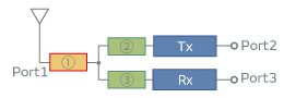
Fig.1. Basic block diagram of a duplexer
On the other hand, in the case of a quadplexer, four filters (two Tx filters and two Rx filters, or one Tx filter and three Rx filters, and so on) with different frequencies are connected to a common antenna node. Its frequency bands that should be taken into account mutually increase to four and matching element number also increases, which causes additional mismatching losses. Furthermore, when a narrow duplex gap duplexer such as that of Band25 is included in the quadplexer, its design difficulty becomes higher degree.
In order to solve those subjects, a matching circuit design method and suitable filter performances have been studied.
III. MATCHING CIRCUIT DESIGN FOR QUADPLEXER
We consider a Band4-Band25 SAW quadplexer. Its frequency bands are as follows; Band4Tx:1710-1755MHz, Band4Rx:2110-2155MHz, Band25Tx:1850-1915MHz, Band25Rx:1930-1955MHz. The duplex gap bandwidths are Band25:15MHz and Band4:355MHz. The gaps between both bands are Band4Tx-Band25Tx:95MHz and Band25Rx-Band4.
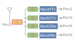
Fig.2. Basic block diagram of a Band4-Band25 quadplexer
Rx:155MHz. In this case, the duplex gap of Band 25 of 15MHz is extremely narrow.
The quadplexer is a 5-port device as shown in Fig.2. Generally, the passband impedance of an antenna port for each filter should be 50ohm and after connecting four filters by using phase shifters and/or some LC parts, the impedance values for counter-bands should be shifted to open positions, which is similar to the duplexer case.
In such procedure, many matching elements corresponding to each filter are required, which results the increase of matching losses. Moreover, in the narrow gap case such as Band25, a steep impedance change from 50ohm to open is required in narrow frequency range. Hence, sophisticated matching circuit design and SAW filter design are required.
For optimizing each impedance value of the filters in corresponding frequency bands, authors studies the tendencies of impedance locus of various kind of SAW filter constructions, and thought out an impedance matching method using jointed impedance conjugation approach. This method is effective for the case using narrow gap quadplexer. Following steps show this matching circuit design procedure:
- In each SAW filter designing stage, impedance values of the antenna port sides for Band4Tx filter, Band25Tx filter and Band4Rx filter are designed to be capacitive impedance near 50ohm in the passband frequencies and open zone(high impedance) in the counter bands (Fig.3(a),(b) and (d)).
- Regarding Band25Rx filter, the antenna port side impedance in the passband is also set to capacitive area near 50ohm and that in the counter bands are set to low impedance zone (Fig.3(c)).
- With connecting the antenna port side of three filters of Band4Tx, Band25Tx and Band4Rx, their joint impedance is shown in Fig.3(e). Regarding Band25Rx, a series inductance is added to the antenna side port in such a way that the locus of the impedance should be set to complex conjugate of the joint impedance of other three filters(Fig.3(f)).
- The nodes of the antenna side port of three filters and the added series inductance of Band25Rx filter are connected to antenna port, thus the synthesized impedance of four filters in each passband are located in almost same position near 50ohm. Finally, a small inductance is added in series to the antenna port for matching to 50ohm(Fig.3(g)).
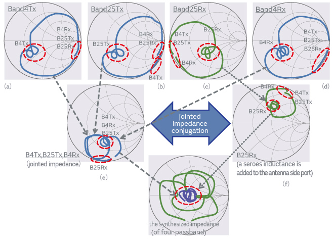
Fig.3. Matching procedure using jointed impedance conjugation for a Band4-Band25 quadplexer
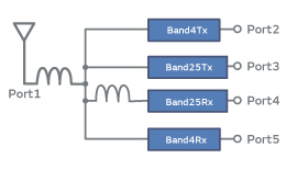
Fig.4. Resulting matching circuit of the Band4-Band25 quadplexer
Figure 4 shows the resulting circuit configuration of the designed quadplexer. By using this method, the matching element is only two parts, which means very small number of parts and leads reduction of additional loss.
IV. SAW FILTER CHARACTERISTICS
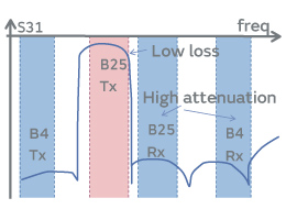
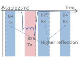
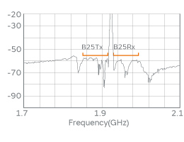
In general, when the number of filters connected to antenna port increases like multiplexers, transmission characteristics are degraded by additional element loss and matching loss in comparison with duplexers. For lower power consumption and higher receiving sensitivity for CA operation of smart phones, higher performance of SAW filters are required. In multiplexer applications, not only lower insertion losses in passband, but also higher impedances in counter-bands leads to improvement of total transmission loss of the multiplexer, as shown in Fig.5.
(a)
(b)
Fig.5. Suitable characteristics of Band25Tx filer for quadplexer. (a) Transmission characteristics, (b) Reflection characteristics.
For these applications, a new high-Q SAW technology, which we name IHP-SAW (Incredible High Performance-SAW), has been developed. This technology includes the energy confinement of SAW and also, temperature drift compensation techniques.
V. EXPERIMENTAL RESULTS
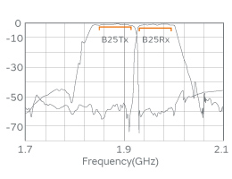
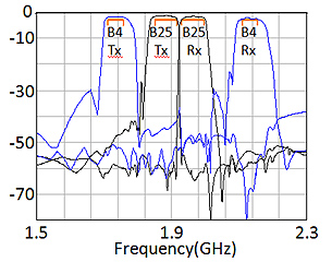
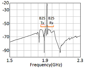
In order to realize a quadplexer, a new Band25 duplexer using IHP-SAW technology has been fabricated using standard ceramic substrate packages, as shown in Fig.6. Its measured electrical characteristics are shown in Fig.7. The ‘Bode’ Qmax [7] of the fabricated IHP-SAW resonator is 3500, which is about three times large as that of a conventional TC-SAW(temperature compensated SAW). The insertion losses in room temperature are 1.5dB for Tx and 1.9dB for Rx. The temperature coefficient of frequency (TCF) is less than 8ppm/deg, thus the insertion losses in full temperature range of -30 to 85deg are 1.9dB for Tx and 2.3dB for Rx. Low loss and very stable performances are obtained. The Tx to Rx isolation levels are 56dB in Tx band and 60dB in Rx band. Reflection characteristic of Tx filter is shown in Fig.7(c). compared with the conventional TC-SAW performance. Higher reflection is realized in the developed duplexer.
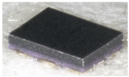
Fig.6 External view of Band25 IHP-SAW duplexer(2.0×1.6×0.6mm3)
(a)
(b)
Red: IHP-SAW,Blue:conventional SAW (c)
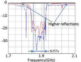
Fig.7 Measured electrical characteristics of developed Band25 duplexer. (a) Transmission performances, (b) Isolation, (c) Reflection of Tx filter.
By using the matching circuit design described in section III, quadplexer characteristics are calculated. In a circuit simulation, experimental S-parameters of the filters and a Q value of 20 for matching inductances are employed. Simulated results are shown in Fig.8. Insertion loss levels of passbands are 2.4dB, 2.8dB, 2.0dB and 2.5dB for Band25Tx, Band25Rx, Band4Tx, and Band4Rx, respectively. Concerning isolation value, for Band25, 58dB is realized in both Tx and Rx bands. While cross isolation is more than 50dB, further improvement has been promoted.
(a)
(b)
(c)
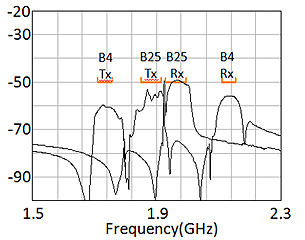
Fig.8 Simulated electrical characteristics of Band4-Band25 quadplexer. (a) Transmission performances, (b) Isolation for band25, (c) Cross isolation.
VI. CONCLUSIONS
CA is an essential technology to increase the mobile data transfer rate and a multiplexer is one of key devices for mobile handsets with CA function.
In this paper, concerning a Band4-Band25 quadplexer, some issues for circuit design and required filter characteristics are discussed. An effective matching circuit design method using the jointed impedance conjugation approach is proposed. Moreover, experimental results of a new type high-Q SAW duplexer named IHP-SAW, with high impedance in out of band and low TCF, are demonstrated. By using these technologies, a high performance Band4-Band25 quadplexer is exhibited with calculated results. Various kind of multiplexers with other frequency bands, such as high bands and so on, are planned to be developed using these technologies.