Chapter 3: What are important DC-DC converter characteristics?
In Chapter 2, we talked about the types of DC-DC converters and their operation mechanisms. The key power inductor parameters, however, cannot be determined from this information alone. In order to understand how converter characteristics work with these parameters, we first need to look into the important DC-DC converter characteristics required by the power inductors.
3.1 Important DC-DC converter characteristics
There are many different characteristics that are required of DC-DC converters. Of these characteristics, the following three affect the performance of power inductors the most:
①Efficiency, ②ripple voltage, and ③load response
Read on to learn more about these characteristics and what they have to do with the power inductor.
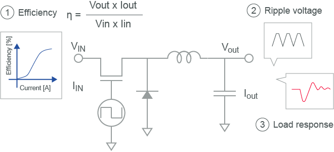
Figure 3-1 Important DC-DC converter characteristics
3.2 Efficiency
First, let’s talk about power efficiency. In the ideal DC-DC converter where there is no power loss, the input voltage is equivalent to the output voltage. If this is achieved, efficiency is at 100%. However, for an actual DC-DC converter, there is power loss equivalent to PDC-DC, making the output voltage lower than the input voltage. Efficiency is demonstrated in the following equation. The lower the PDC-DC value, the better the efficiency of the converter.
The efficiency mentioned in this chapter refers not only to the efficiency of the power inductor but also to the efficiency of the DC-DC converter as a whole.

Figure 3-2-1 DC-DC converter power consumption
Figure 3-2-2 gives an example of a measurement of efficiency. Because the current supplied to the load (Iout) changes depending on the application of the converter, this is often used as the X axis value.

Figure 3-2-2 Example of DC-DC converter efficiency
PDC-DCpower consumed by the DC-DC converter can be mainly broken down into PIC, PPI、Pother, and Pother power. PIC is power loss that occurs in the IC, and includes the losses that occur from switching and on-resistance. PPI is the loss that occurs from the inductor. Pother is the loss that occurs from the capacitor ESR as well as other instances of power loss.
While it also depends on the operational requirements and IC performance, PPI can make up about 50% of the PDC-DC power consumed in a converter. This affects the efficiency of the power inductor greatly, which creates a demand for power inductors to have low power loss as a characteristic.

Figure 3-2-3 Power Load resistance Breakdown of power consumption
The inductor power loss PPI can be broken down into DC loss and AC loss, as demonstrated in the equation below. DC loss shown here is power loss from a direct current while AC loss is power loss from an alternating current. DC loss is proportional to Rdc (direct current resistance) because it is the conductor power loss from a direct current passing through a coil of wire. Meanwhile, AC loss is proportional to Rac (alternating current resistance) and is defined as the power loss in the conductor from an alternating current passing through a coil of wire. AC loss includes power loss in the core, which is also referred to as iron loss. At high frequency, power loss in the conductor also tends to increase due to the skin effect. Rac here is defined in the following equation. Rac1 is the conductor resistance that increases due to the skin effect while Rac2 is the resistance of the core material.

Figure 3-2-4 Breakdown of inductor power loss
Figure 3-2-5 is a depiction of AC loss and DC loss in relation to the load current. The AC components in the current supplied to the inductor are determined by the input/output voltage and frequency. Because of this, the amount of AC loss is not altered greatly by changes to the load current. DC loss, on the other hand, is proportional to the square of the load current. The DC loss is low due to the small current at low load, but it increases greatly when the load current increases. Therefore, AC loss is dominant in low load density areas, and DC loss is dominant in high load density areas.

Figure 3-2-5 Power loss through low load or high load dominance
DC-DC converter Inductance Efficiency Simulator Operation frequency Input voltage Output voltage Output current Efficiency evaluation through simulation
- Simulator : LTSPICE
- DC-DC converter : Linear Tech LTC3612
- Operation frequency : 4MHz
- Input voltage : 3.6V
- Output voltage : 1.8V
- Output current Iout : 10m~3A
Figure 3-2-6 Efficiency evaluation through simulation
Figure 3-2-7 shows the resulting efficiency when Rdc is between 0.01Ω and 2.0Ω. Because Idc is small at low load, there is not a big change to efficiency even when Rdc changes. However, because Idc is large at high load, a change in Rdc has a large impact on efficiency.
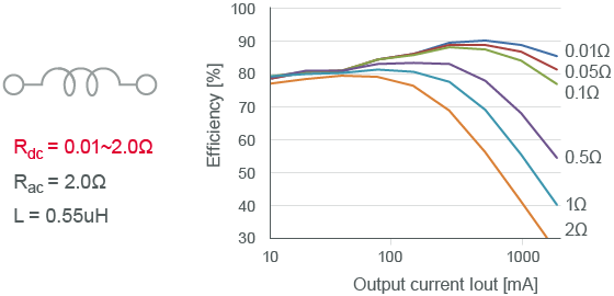
Figure 3-2-7 How Rdc affects efficiency
The resulting efficiency from changing Rac from 0.1Ω to 10Ω is shown in the following. Because the amount of Rac accounts for the amount of AC loss, low load, which is when AC loss is dominant, greatly impacts efficiency. However, because DC loss is dominant due to the increase in Idc at high load, there is not a big change to efficiency even when there is a change to Rac.
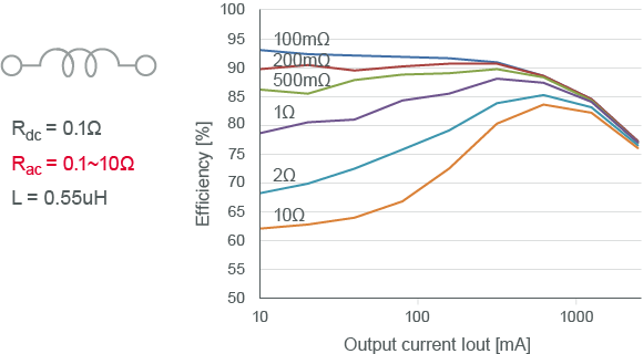
Figure 3-2-8 How Rac affects efficiency
Finally, we have the resulting efficiency when the inductance is between 0.22μH and 2μH. Like Rac, inductance greatly impacts AC loss. Therefore, there is a great impact on efficiency at low load and little change to efficiency at high load.

Figure 3-2-9 How inductance affects efficiency
Inductance impacts efficiency because the AC components in the current supplied to the inductor are determined by the inductance. The slope of the triangular wave current is proportional to the inverse of the inductance. Therefore, if the inductance is high, the current amplitude decreases, and AC loss is reduced.

Figure 3-2-10 Why inductance impacts efficiency
Considering what was mentioned up until this point, important characteristics for reducing inductor power loss are low Rac and high inductance at low load, and low Rdc at high load.

Figure 3-2-11 Inductor characteristics required for high efficiency
3.3 Ripple voltage
Next, let’s talk about ripple voltage. Ripple voltage is the small, fluctuating voltage components in the output voltage. Ripple voltage occurs when this voltage fluctuation synchronizes with the switching frequency. Ideally, it is best for there to be zero ripple voltage. This is because operational problems could occur in the system if the ripple voltage fluctuations are large and the voltage becomes lower than the minimum operating voltage of the system on the load side. In recent years, DC-DC converters are being made to work with larger and larger currents at lower and lower voltages, creating the need for voltage supply that is even more stable.

Figure 3-3-1 What is ripple voltage?
Just like we did with efficiency, let’s take a look at the way changes in inductance affects ripple voltage.
- Simulator : LTSPICE
- DC-DC converter : Switch model
- Operation frequency : 4MHz
- Input voltage : 3.6V
- Output voltage:1.8V
- Output current Iout : 2A
- Inductance : 0.47/1.0/2.2µH
Figure 3-3-2 Simulated ripple voltage evaluation
We can see from Figure 3-3-3 that the ripple voltage is often kept low when the inductance is high. As was mentioned in Chapter 2, the ripple current supplied to the inductor is reduced when the inductance is high. As a result of this, the output ripple voltage also becomes lower. However, we need to be careful of the ability of DC superposition characteristics to reduce inductance. If parts with a poor DC superposition are employed, the inductance is reduced, increasing the ripple voltage. Therefore, while it is the obvious, an Isat larger than the load current needs to be used.

Figure 3-3-3 Ripple voltage and inductance
3.4 Load response
The final important characteristic we are covering in this chapter is load response. DC-DC converters provide a constant output voltage, with the current supplied to the load changing as appropriate depending on the converter application. The output voltage temporarily increases or decreases when there is a sudden change in the current. Because this fluctuation in voltage is proportional to the inductance, it affects the performance of the power inductor greatly. The voltage fluctuation and the time it takes to return to the preset voltage is referred to as the load response characteristic, and a return to the preset voltage with few voltage fluctuations in a short period of time is considered a good load response. Like the ripple voltage mentioned above, this is a critical characteristic for DC-DC converters that require a stable voltage supply.
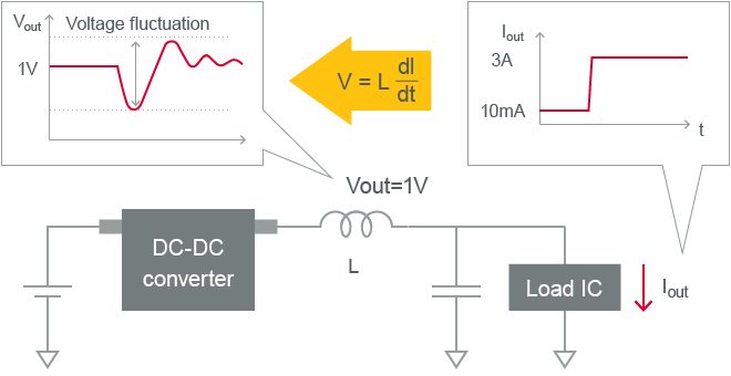
Figure 3-4-1 What is load response?
Here, a DC-DC converter evaluation board is used to evaluate the load response characteristics at different levels of inductance.
- DC-DC converter : TPS62660/TI
- Operation frequency : 6MHz
- Input voltage : 3.6V
- Output voltage : 1.8V
- Output current Iout : Change from 0A to 0.35A
-
Inductance : 0.47/1.0/2.2µH
(Evaluation of load response characteristics using an evaluation board)
Figure 3-4-2 Evaluation of load response characteristics using an evaluation board
From the measurements, we can see that the output voltage fluctuates when the load current increases or decreases. As the inductance of the power inductor determines the load response characteristics, a lower inductance produces a smaller fluctuation in the output voltage, allowing for a good load response.

Figure 3-4-3 Load response and inductance
3.5 What these characteristics have to do with the power inductor
In sections 3.1 to 3.4, we talked about the important DC-DC converter characteristics of efficiency, ripple voltage, and load response and explained the kinds of characteristics required by power inductors. However, while using parts with high inductance may improve efficiency and ripple voltage, it negatively affects the load response. There is also the problem of a high inductance causing an increase in Rdc and Rac. Because each power inductor characteristic is linked to a tradeoff, power inductors need to be chosen carefully to create a good balance of characteristics that work with each operational requirement and objective.
The Murata DC-DC Converter Design Support Tool is available on our website to help you choose the power inductors that will work for you. This tool can help you choose a power inductor based on the DC-DC converter characteristics explained in this chapter. In Chapter 4, we will talk more about this tool and provide examples of different power inductors in application.
Figure 3-5 Summary of key power inductor parameters
|
Rdc |
Rac |
L |
| Efficiency (At low load) |
- |
Smaller is better |
Larger is better |
| Efficiency (At high load) |
Smaller is better |
- |
- |
| Ripple voltage |
- |
- |
Larger is better |
| Load response |
- |
- |
Smaller is better |