Creating the Next Generation of Connected and Autonomous Vehicles Starts with the Smallest Components
The fundamental elements that define the nature of an automotive vehicle have remained relatively unchanged since its inception until recently. In essence, a car was a means of personal transportation powered by an internal combustion engine (ICE) and perfect for transporting one or more individuals. It was a standalone solution controlled by the driver with limited mechanical and electronic assists present.
However, there has been a significant shift in recent years as vehicles transition from standalone fossil fuel burning options to electric vehicles (EVs) that are integrated into a larger network. This aim to create truly intuitive mobility solutions can be encompassed by the acronym CASE – Connected, Autonomous, Shared and Electric. But as we enter the next generation of CASE era cars, a number of new technical challenges arise that must be overcome if the automotive industry is to realize this ambitious goal.
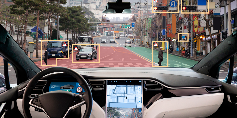
One challenge at the core of this evolution is the near exponential growth in vehicle communications. CASE era vehicles need to have robust in-vehicle networks (IVN) capable of connecting control modules and the critical sensors that underpin advanced driver assistance systems (ADAS), as well as communication beyond the vehicles chassis in the form of vehicle-to-vehicle (V2V), vehicle-to-infrastructure (V2I) and vehicle-to-everything (V2X) systems.
This core requirement for greater communication has a profound impact on vehicle electronics, increasing both the volume of wiring and the noise considerations, an issue that is also amplified by the presence of high-voltage AC motors. Therefore, the automotive industry requires elegant solutions that are capable of both streamlining system complexity and are immune to noise.
Evolving Vehicle Networking – from Domain to Zonal Architecture
Traditionally, vehicles have relied on domain-based architecture, whereby domain control units (DCUs) were responsible for overseeing discrete aspects of the vehicle’s functionality, such as infotainment, engine, chassis, and ADAS. However, with the increase in component count and the advancement of vehicle intelligence, this architecture has become unmanageable.
The need for components from different parts of the vehicle to connect back to centralized DCUs has become too intricate and heavy. Additionally, the speed of the IVN has become an issue, especially with ADAS systems and dynamic lighting, as their requirements surpass the relatively low data rate of 1 MBit/s provided by the existing vehicle controller area networks (CANs).
Zonal Architecture
With the aim of enhancing connectivity and control, new vehicles are adopting a design shift towards Zonal control. This approach is based on the position of the equipment within the vehicle, rather than its functionality. Zonal architecture offers several advantages, including better scalability and the provision of a software-driven framework. By bringing control units closer to sensors and devices, it simplifies cabling and reduces complexity in the connections between gateways and hosts.
In zonal systems, communication across the vehicle is underpinned by higher-speed ethernet and CAN-FD (Flexible Data-Rate) networks. This ensures that sensors and controllers can communicate seamlessly, regardless of their position or wiring harness connection point on the vehicle. As a result, it significantly reduces the complexity of cables compared to domain-based control. Furthermore, this architecture allows for localized control at the vehicle’s edge with distributed System-on-Chips capable of controlling basic vehicle functions, reducing the data that is communicated across the IVNs.
In order to realize CASE era cars, fast and robust ethernet backed zonal architectures are needed, along with other intelligent solutions which are capable of reducing cabling complexity and working in noisy EV environments.
Ensuring Reliable High-Speed Networks
The noise that can impact high-speed IVNs consists of two types: normal mode noise and common mode noise. Ferrite beads, capacitors, and resistors are used to remove normal mode noise, while common mode choke coils (CMCCs) are used to remove common mode noise.
Common mode noise is generated when a phase shift occurs in a differential signal in a cable, connector, or other part. Differential signals are frequently utilized within IVNs and so high-quality CMCCs are required.
To meet this requirement, Murata offers products that meet the standards for CAN/CAN-FD, vehicle-mounted Ethernet, and other vehicle-mounted networks, providing exceptional noise suppression in a compact form factor. Historically CMCCs in CAN networks were large-size toroidal types where copper wires are wrapped around a ring magnet or a 4532 (4.5 mm x 3.2 mm) size automatic-winding type. Murata was among the first to develop and release a miniaturized 3225 (3.2 mm × 2.5 mm) size automatic-winding CMCC.
For CMCCs in CAN and Ethernet networks, reduced loss is required, and the characteristic known as mode conversion takes on even greater importance. The mode conversion characteristic is an indicator of the level of conversion from normal mode to common mode, and a smaller value signifies a decreased probability of common mode noise occurrence. A CMCC is made up of two coils combined together, but in order to enhance the mode conversion characteristic, the symmetry of this pair of coils needs to be enhanced. Murata improved the coil design and winding method of their automotive CMCCs to enhance symmetry, resulting in improved performance.
To address the technical requirements of both signal and power lines within the various systems deployed in CASE era vehicles, Murata produces a wide range of multilayer type and winding type. This includes the DLW32SH510XF2 or DLW32SH101XF2 which is designed specifically for CAN-FD signal lines or the DLW32MH101XT2 which is compatible with 1000Base-T1(1000Mbps) ethernet.
Combining Signal Line and Power Line Camera Connections
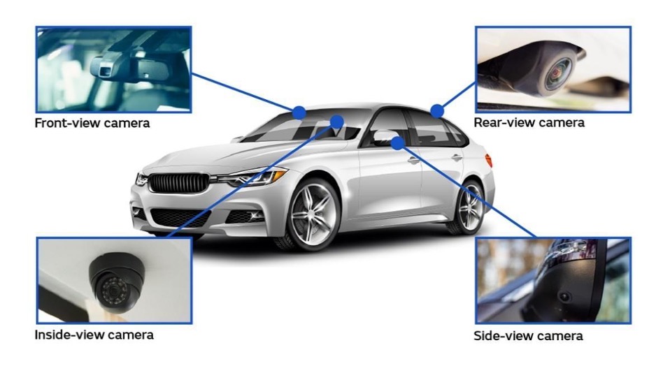
Cars equipped with multiple automotive cameras have become a standard offering in the market in recent years (Figure 2). Numerous automotive cameras are installed in self-driving vehicles to recognize and interpret the external environment.
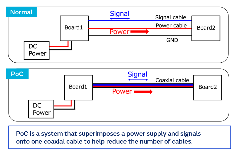
In order to output the captured data, it is necessary to connect these cameras to both a power supply line and a signal line. But this twin connection requirement across countless on-board cameras can lead to a significant number of cables, increasing vehicle build complexity and weight.
Many automotive manufacturers, including OEMs and Tier 1 suppliers, are actively adopting power over coaxial (PoC) technology to reduce the number of cables required for automotive cameras. This technology integrates both signal lines and power supply lines, as illustrated in Figure 3.
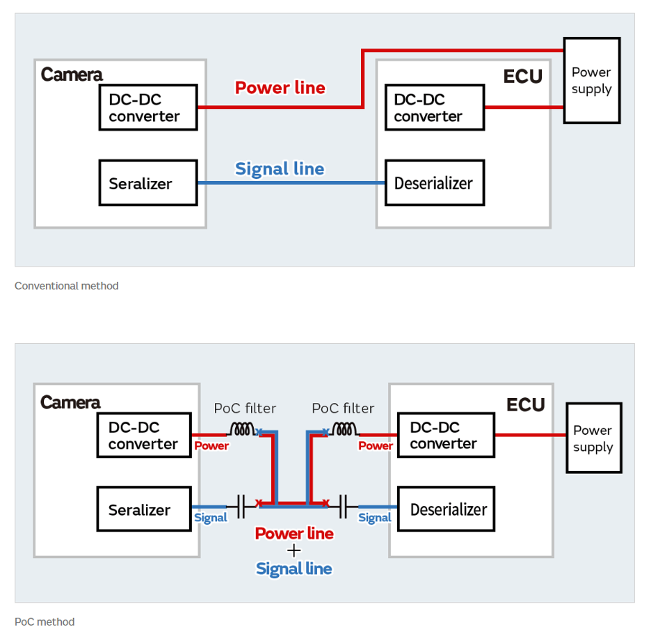
To introduce PoC, it is necessary to include a circuit known as a 'Bias-T circuit' on both the transmitting and receiving sides, as well as on the power supply (Figure 4).
The purpose of a Bias-T circuit is to separate the high-frequency signal from the DC power supply on the low-frequency side. The circuit consists of an inductor that filters out high-frequency video signals and a capacitor that filters out the DC power supply.
When creating a Bias-T circuit, it is essential to select an appropriate inductor to serve as a PoC filter. This inductor should have precise characteristics that allow for the effective separation of signals and the power supply. Failure to achieve adequate separation may result in the unwanted flow of high-frequency signals into the power supply circuit, causing disruptions and malfunctions in connected devices. When selecting an inductor, it is important to choose one that acts as a high-impedance filter across a broad frequency range, from several MHz to several GHz. However, it can be challenging to find a single inductor that covers such a wide band. Typically, the desired characteristics can be achieved by combining multiple inductors and ferrite beads, as shown in Figure 5.
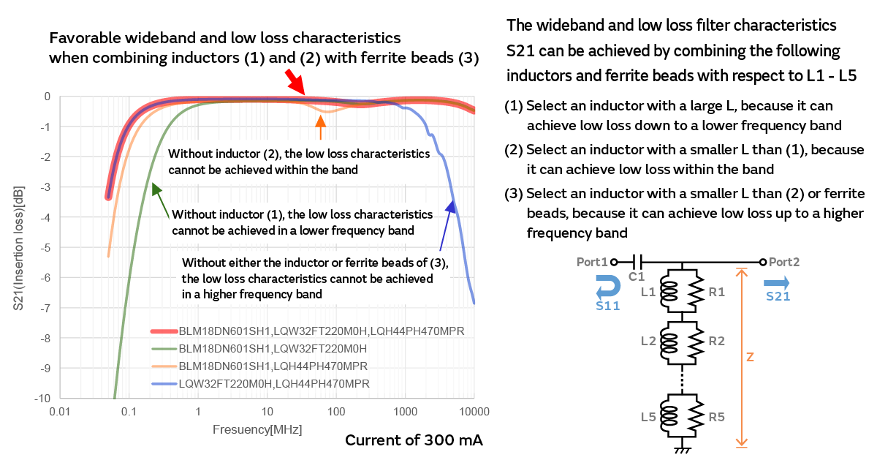
Choosing the best combination from a diverse range of inductor products is a time-consuming and demanding task. The first step involves selecting components that are suitable for the frequencies of the signals, the power amperage, the ambient temperature, and other relevant conditions. But it is not possible to decide simply by summing up the characteristics of each individual component at that specific time. This is due to the presence of parasitic capacitance on the circuit board, as well as the impact of parasitic inductance and the characteristics of the coaxial cable that links to the circuit board. These factors greatly influence the behavior within the high-frequency range.
Simplifying Selection
When choosing components to use, it is important to consider the specifications of the automotive camera system and the characteristics of the circuit board it will be mounted on. It is also necessary to test different combinations of components through simulation to find the best solution.
Murata has created the Bias-T Inductor Selection Tool (BIST) to streamline the component selection process. Through the configuration of the minimum number of conditions, the tool is able to identify and present the optimal combination of components, specifically inductors and ferrite beads, manufactured by Murata. By using BIST, the effort and time needed for component selection is greatly reduced, allowing for the selection of suitable components, even without specialized knowledge.
Conclusion
Murata has established a strong reputation in the automotive market for consistently producing high-quality CMCCs and inductors in large quantities, surpassing the quantity requirements set for vehicle-mounted components. As vehicle-mounted networks continue to advance and become more widely used, the demand for these components is expected to rise significantly, and Murata is well positioned to meet this increased demand.
The significant evolution of cars based on CASE requires the integration of various peripheral technologies to implement advanced features. These include artificial intelligence (AI) as the self-driving car's brain, as well as the inverter and battery, which serve as the heart of electric vehicles. However, in order to be one of the pioneers in equipping cars with advanced vehicle-mounted networks and entering the market early, it is crucial to first prepare noise suppression components and similar products. Murata's automotive inductor and CMCC products, as well as technical support for initiatives like BIST enable the implementation of advanced technology, helping manufacturers to usher in the next generation of vehicles.