Understanding EMC filter design for railway rolling stock applications
All railway electrical equipment installed onto rolling stock (train) and trackside (off-train) equipment applications must be approved to BS EN50155:2017. Within the scope of this standard, many parameters must be designed and tested to protect against electromagnetic interference (EMI) and ensure railway subsystems are electromagnetically compatible. Additionally, a subset of standards is also called upon, such as EN45545 for fire protection, EN60068 for environmental testing, and EN61373 for shock and vibration. This article focuses on the EMI section of the EN50155:2017 standard, specifically for rolling stock.
Railway standards for EMC of rolling stock equipment
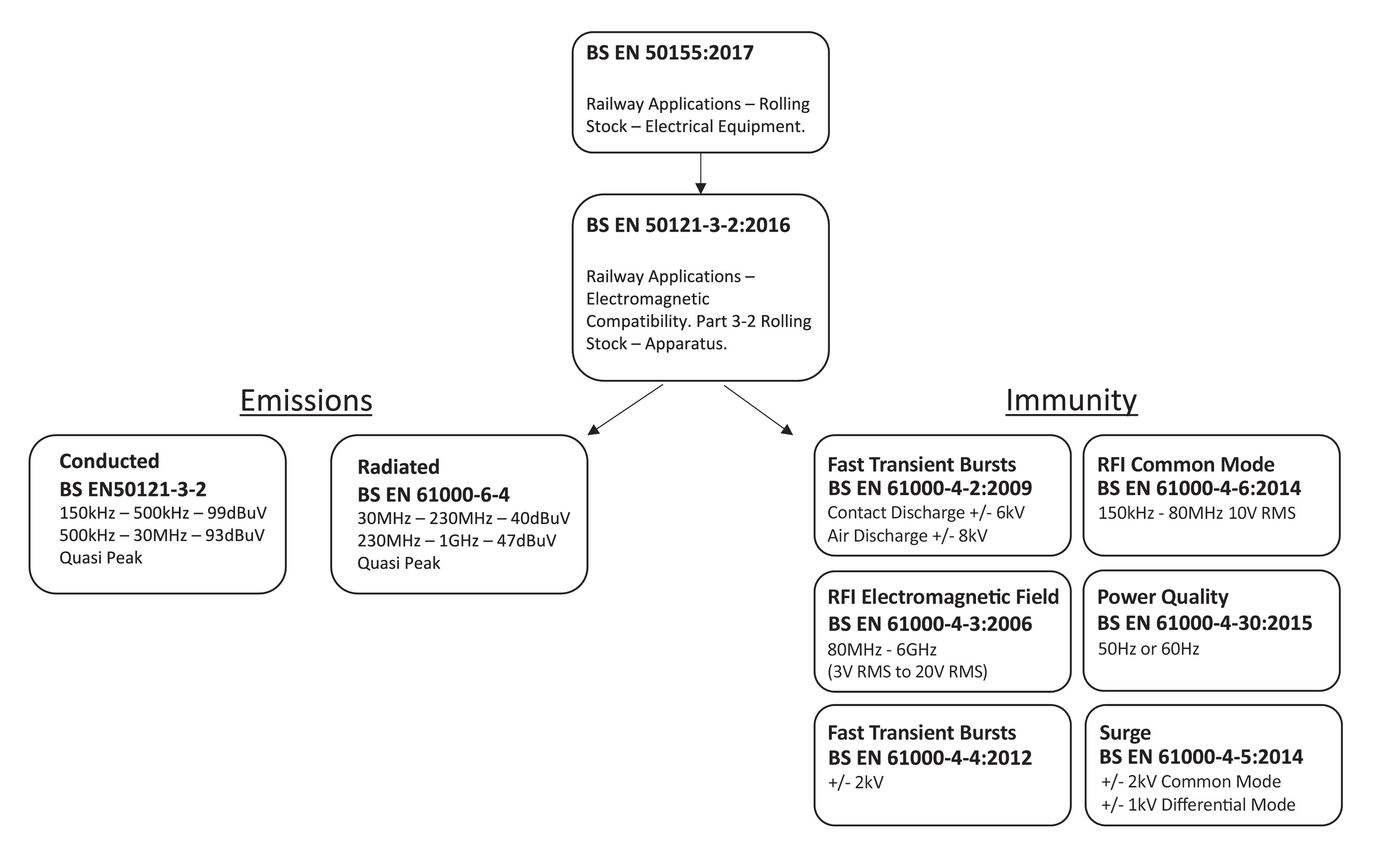
The generic railway standard EN50155:2017 references the standard that defines EMI conformity, which is EN50121-3-2:2016. This standard then calls up industrial sub standards for emissions and immunity, as shown in Figure 1.
Within the scope of the EN50155:2017 standard, three performance criteria levels (A, B and C) must be met. The type of equipment, its location and function, determine which performance level is required, see Figure 2.
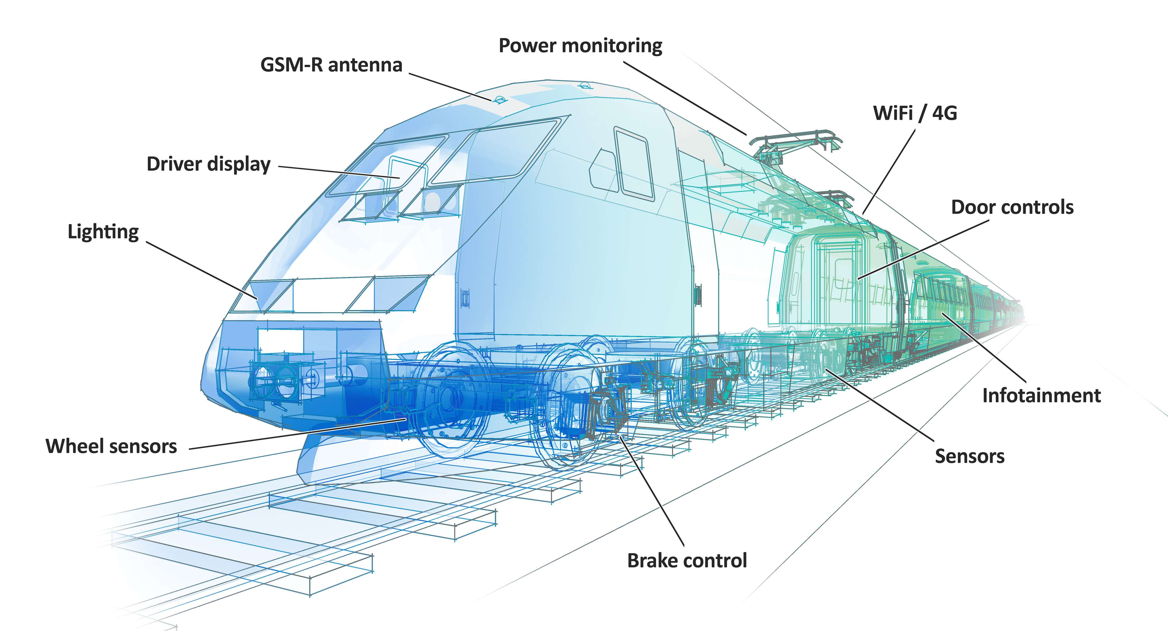
For example, a safety-critical function such as a braking system must meet the highest level, that is, performance criteria A. At this level, the equipment must continue to operate as intended, with no degradation of performance or loss of function allowed. A non-critical application, such as a passenger infotainment system, can fall under performance level criteria C. Here, temporary loss of function is allowed whereby following an event the equipment can be automatically or manually restarted. At performance criteria B, performance degradation of the equipment is allowed; however, changes in the actual operating state or stored data are not allowed.
Voltage transients and interruptions
Power can be supplied to rolling stock systems in many ways. AC power can come from auxiliary power converters, overhead lines or a third rail. The EN50155:2017 standard primarily focuses on DC power from an onboard battery, which typically requires a DC-DC converter. The primary technical concerns of the standard for these DC battery-supplied systems are battery voltage range, transient voltages, and voltage interruptions (see Figure 3).
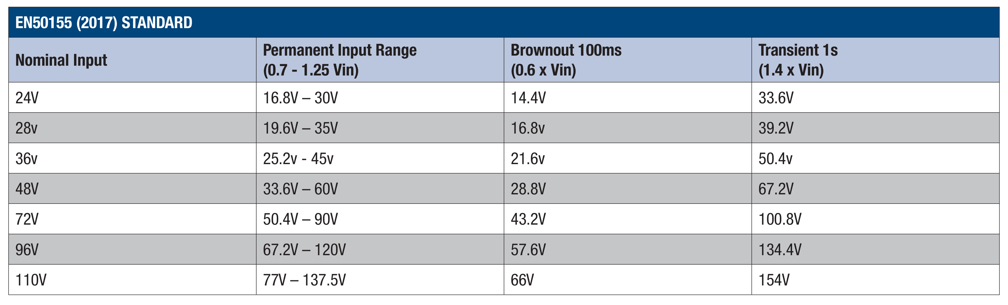
The nominal battery voltage has a variant input voltage range, due to charging and discharging of the battery. There is also a transient range specified, which is a result of load dump, load source and starting of the engine in emergency situations on the bus voltage.
Temporary supply voltage interruptions can result from a short circuit or overload on the overhead lines, which need resetting. The cranking of the combustion engine can also cause interruptions to the supply voltage, if it is a diesel-powered train.
Three interruption classes are defined in the EN51055:2017 standard, depending on the application and its intended use. For class S2 and S3 requirements, additional hold-up capacitance is required for the DC supply voltage.
The DC-DC converter does not need to meet the EN50155:2017 standard, as it is a component within the final application. However, it must meet the requirements for voltage transients and other environmental conditions, so when it is included in a system or application, the end equipment will meet the standard.
Types of DC-DC converters
There are two main styles of DC-DC converters used on rolling stock applications.
Board mount DC-DC converters will meet the voltage transient range specified in the EN50155:2017 standard and the other environmental requirements. However, it will need additional EMI circuitry to meet the requirements of EN50121-3-2:2016. Chassis mount DC-DC converters, on the other hand, cover all the requirements of the EN50155:2017 standard, including EMI.
Although chassis mount DC-DC converters may be more straightforward to install and maintain, board mount types are often selected for their compactness and cost-effectiveness. Therefore, understanding EMC filter design according to the requirements of EN50121-3-2:2016 is crucial. Figure 1 provides the conducted and radiated emissions limit levels, as well as the immunity limit levels.
EMC filter circuit design basics
When designing an EMC filter, the overall objective is to meet the requirements set out in EN50155:2017 for conducted emissions and the immunity standards according to EN50121-3-2:2016 and the EN61000-4 series of sub standards.
First, we need to determine the maximum input current the DC-DC converter will handle, which will affect the filter component ratings. If it has an input voltage range of 16V to 160V with 250W of output power, a switching frequency of 240kHz and a worst-case efficiency of 87%, then the maximum input current will be:
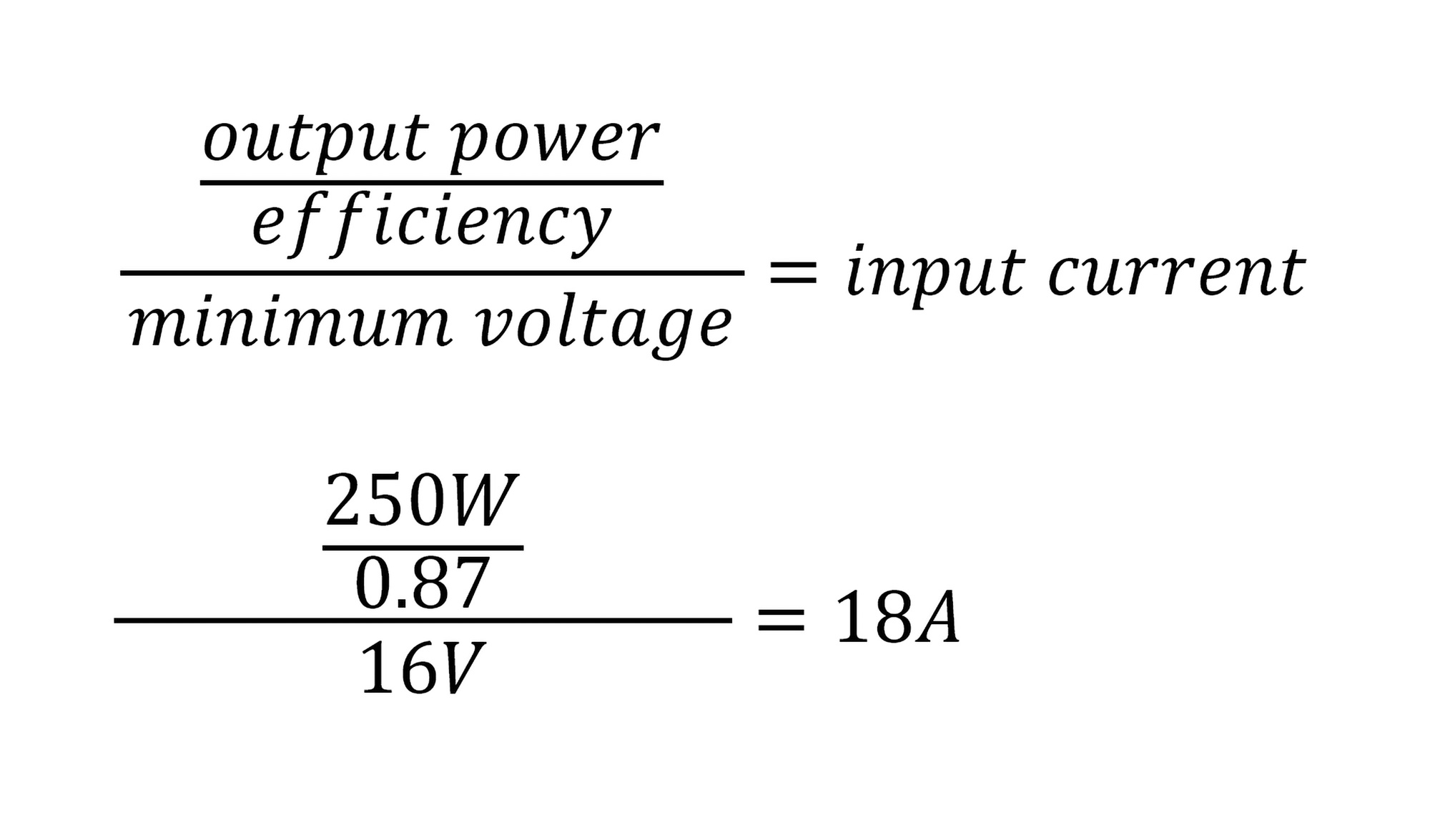
This means that the inductors, connectors, fuses, and PCB traces must be able to operate at a minimum input current of 18A. Component derating is crucial to prevent component failure and ensure the filter maintains its performance throughout its operational life. Also, the input voltage transient range must maintain operation at 14.4V for 100ms, as shown in Figure 3.
A metal oxide varistor (MOV), which is a non-linear surge suppressor, and a silicon tranzorb transient voltage suppressor (TVS) are included within the circuit for immunity protection (see Figure 4). The purpose of both devices is to trigger into conduction mode upon detecting a surge, transient or ESD event, suppress the event and then return to normal mode operation and prevent the transient damaging other circuitry.
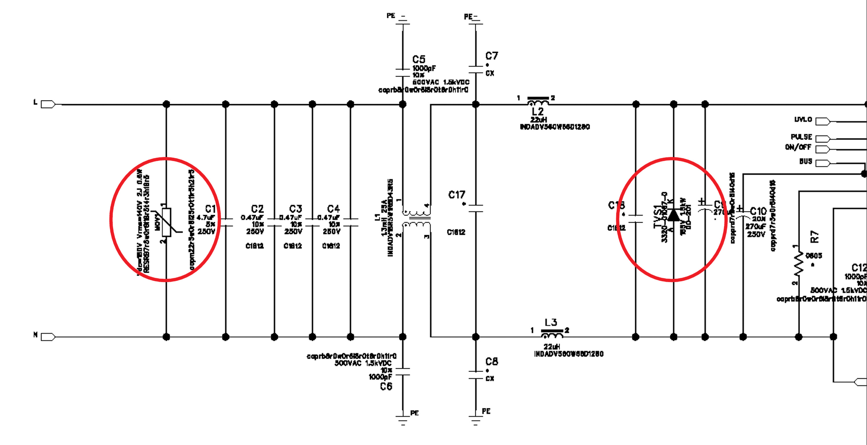
The MOV is positioned directly at the input as it exhibits a higher dynamic resistance and slower turn on characteristic that lends itself well to front line surge events, the tranzorb is positioned after the common mode choke (L1) and differential mode chokes (L2 and L3) as it provides a much sharper dynamic resistance resulting in quick trigger conduction of any transients passing through after the MOV, the inductors provide a resistance path also reducing the transient level.
The MOV is chosen based on the following parameters - the maximum input operating voltage of the circuit is 160VDC, allowing for a 10% headroom on the maximum voltage of 180VDC. The source impedance is 42Ω, so the power of the device will be:
These pulses are applied positively and negatively for a minimum of five in each polarity.
The Tranzorb chosen is a 185VDC (1.5kW) rated device. The input capacitance directly at the input to the DC-DC converter’s 270µF electrolytic capacitor also has a resistive damping effect on surge and transients.
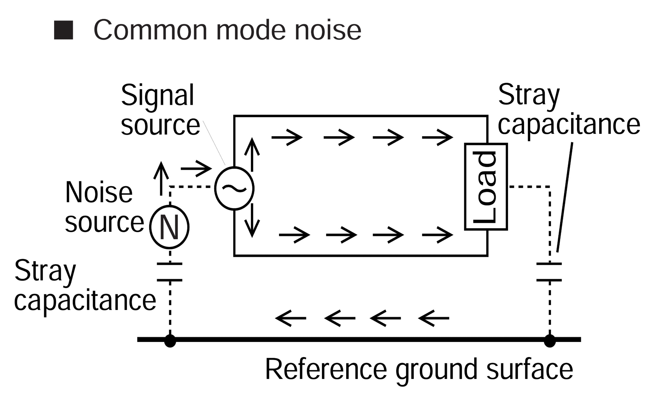
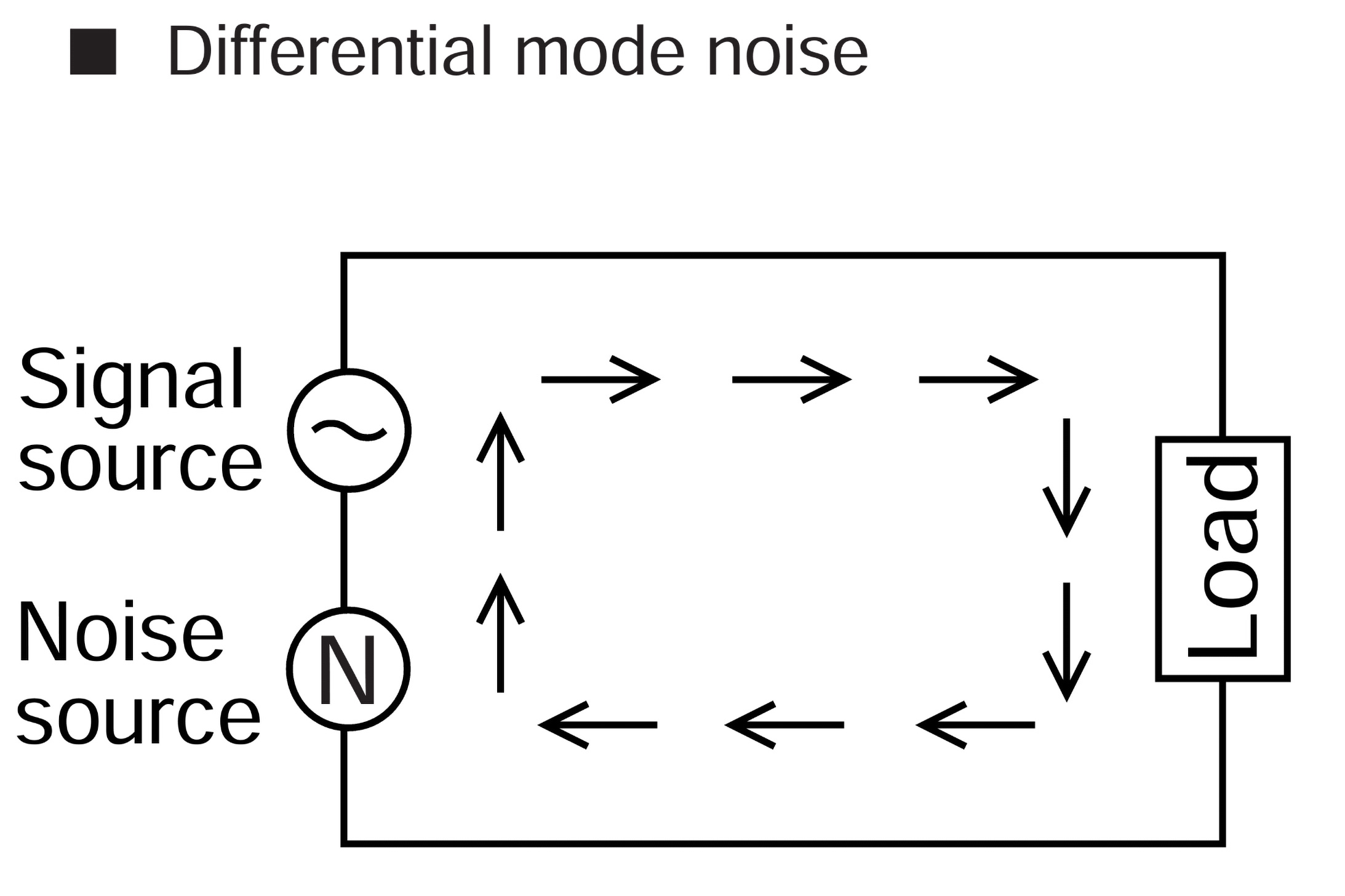
Common mode noise is the signal that flows simultaneously on both positive and negative power lines. The noise is equal on both lines and is added together to result in common mode noise. Differential mode noise is defined as the noise that appears on two lines of a closed loop that flow in opposite directions, one voltage minus the other voltage is the differential voltage (see Figure 5).
When debugging EMI issues, it is important to understand what type of noise you are dealing with to resolve relevant noise issues. It is also essential that the output impedance of the proposed filter is less than the input impedance of the DC-DC converter to prevent oscillation and resonance as per Middlebrook’s theorem, usually by a factor of 10.
Differential mode filter design
We have a 250W DC-DC converter with 90% efficiency, a switching frequency of 240kHz and an input voltage range of 16VDC to 160VDC. For our example filter design, it has a nominal battery voltage supply of 110VDC.
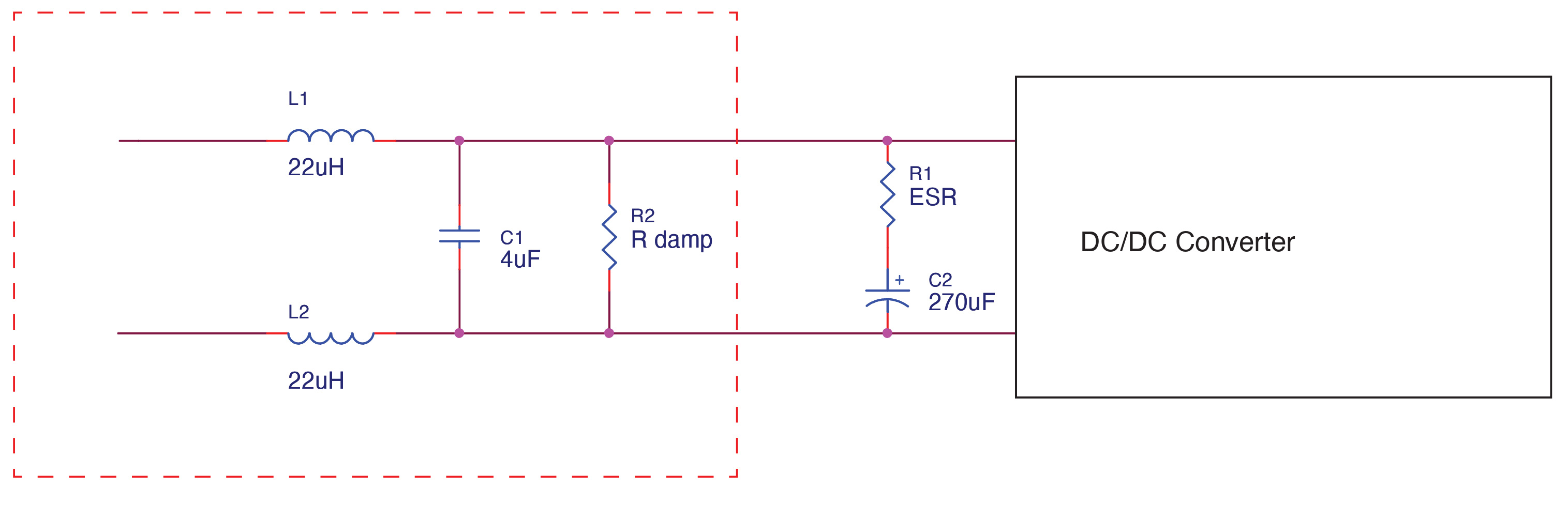
Design of the differential mode section begins with adding an LC filter directly to the input of the DC-DC converter. The differential inductor value must be balanced between the two lines, which means two separate inductors. There is always a bulk capacitor directly at the input of the DC-DC converter, which ensures stability of operation of the converter, and to add input source impedance to prevent instability with the input filter or the input source and cables, etc. The inherent ESR of this capacitor can substitute or count towards the value of the Q damping resistor.
First, we calculate the input impedance of the DC-DC converter:
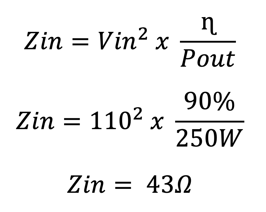
Using the Middlebrook theorem, the output impedance of the filter should be 1/10th of the input impedance of the input impedance of the DC-DC converter, which will be 4.3Ω.
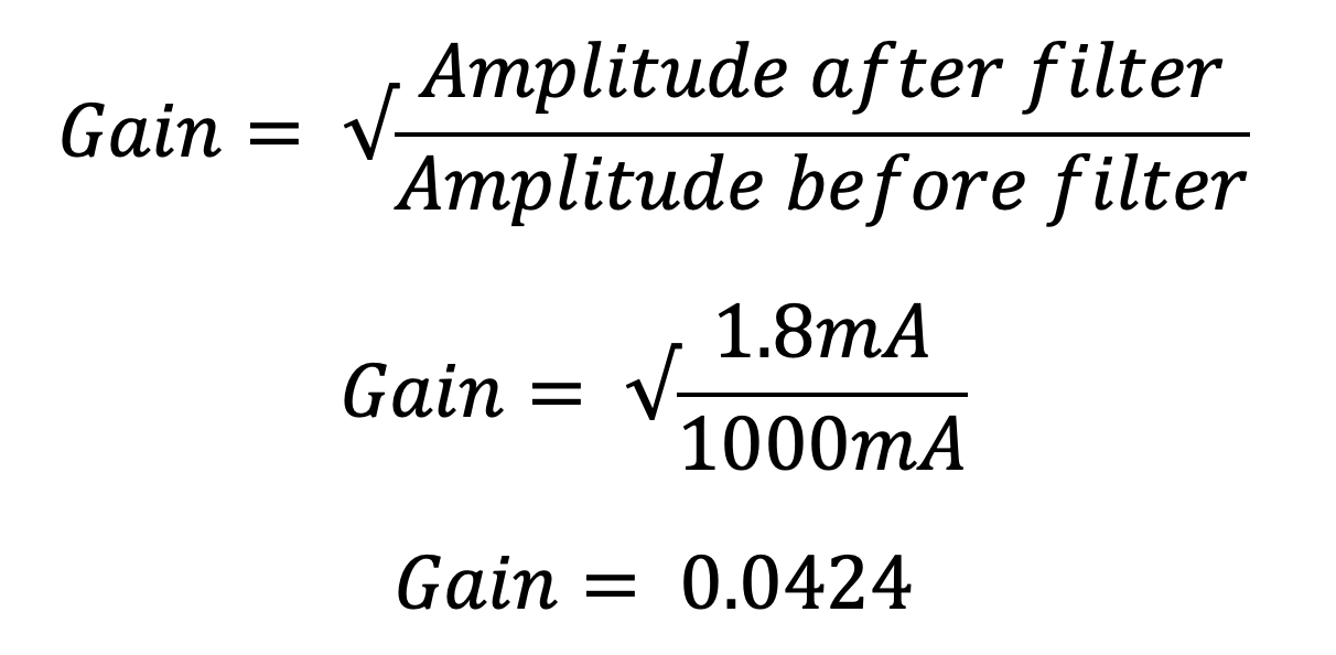
Then, we need to calculate the Gain value:
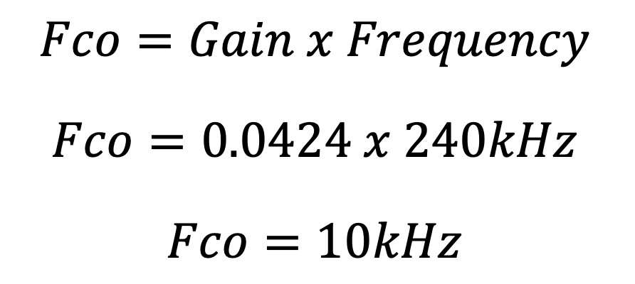
Finally, we calculate the frequency cut off:
Now that we have calculated the impedance and frequency cut off, we can substitute these values onto an impedance paper to produce the results for L and C, see Figure 6.
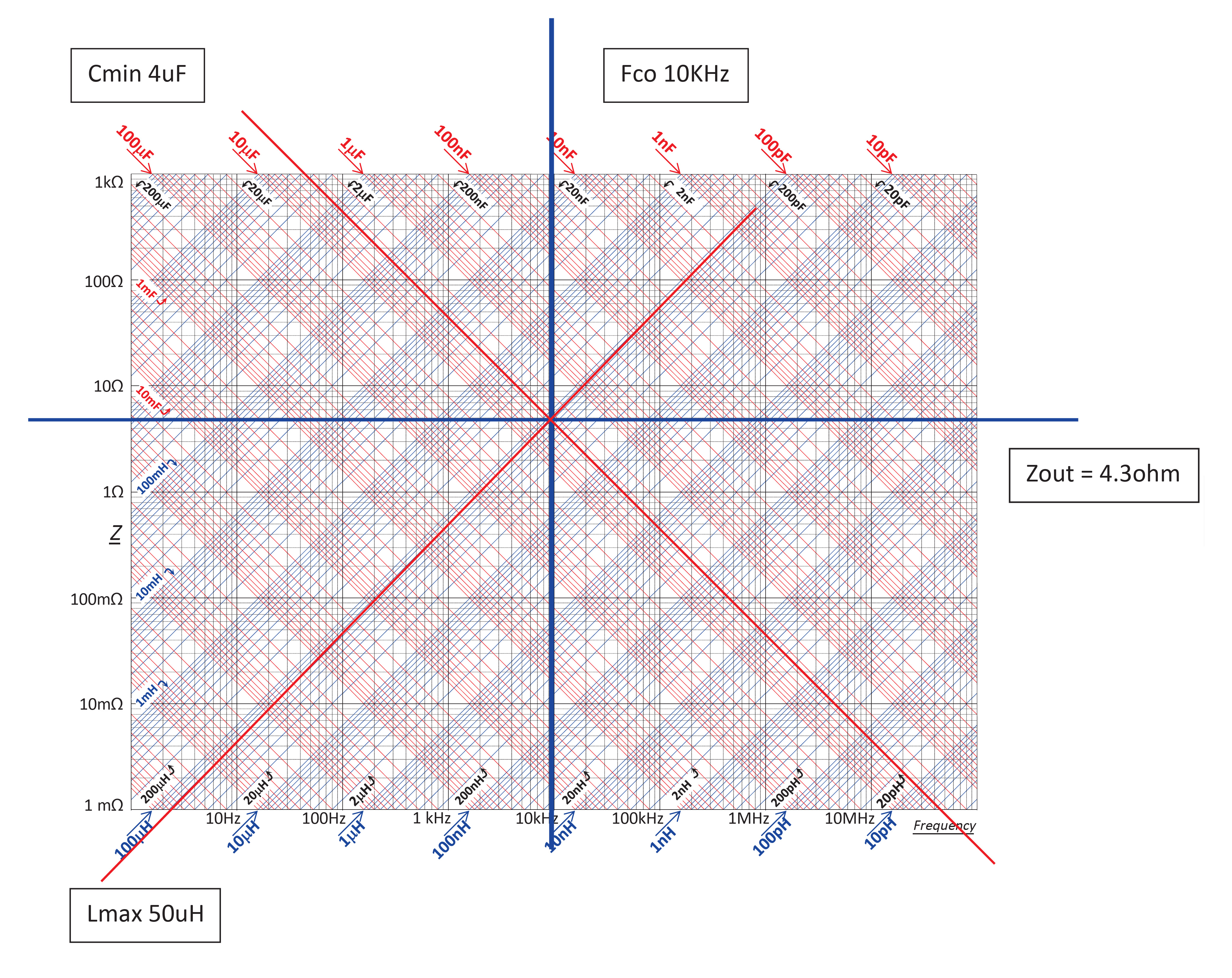
Using the impedance paper, we can easily calculate and manipulate the different component values using the Fco and impedance parameters. The values shown are 4µF (min) capacitance and 50µH (max) inductance. Remember to split the inductance value across each line.
Now that we know the values of L and C, we can calculate the damping resistor. Remember to factor in the ESR of the input capacitor. (sometimes this is enough for the damping resistor).
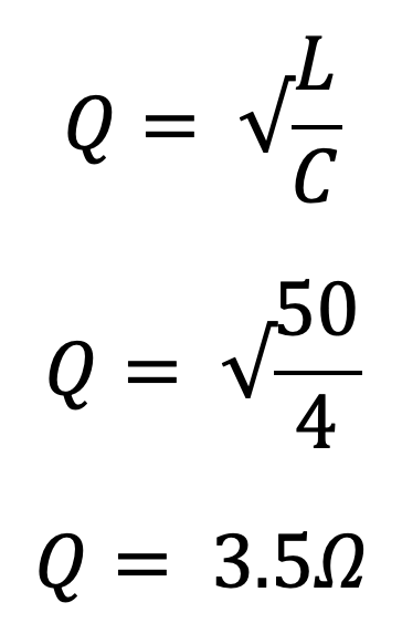
The final calculated circuit is shown in Figure 7.
Note: The calculated damping resistance of 3.5Ω would not be applied directly across the input of the DC-to-DC converter (where R damp is shown in figure 7). In this example the ESR (Equivalent Series Resistance) of the 270uF capacitor is sufficient.
Common mode filter design
Now we look at the common mode components. Common mode noise is prevalent around 5MHz and above, so choosing the value of L and C is based around this figure.
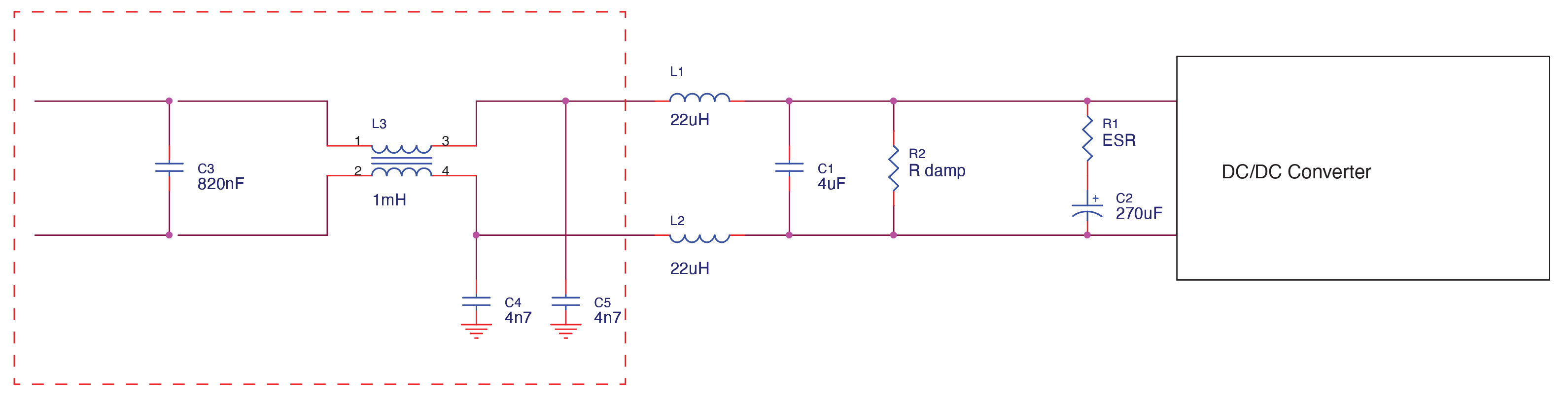
In this example, we chose a 1mH 5A common mode choke that had a differential inductance of 10µH, so an additional 40µH differential inductance was chosen (2 x 22µH preferred values).
To suppress common mode noise to ground, there must be some capacitive path to ground after the common mode choke, this forms the basis of an LC filter. As the filtering is above 5MHz, we know that the Fco of the common mode filter is approximately 50kHz.
The equation used to calculate Fco:
Which can be rearranged to determine the capacitance of the Y capacitor:
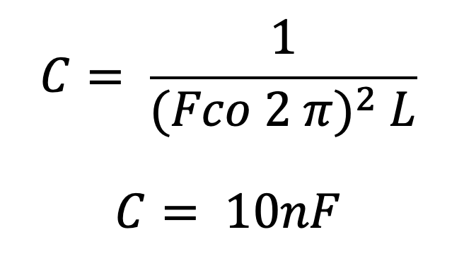
Using two Y capacitors, this value is split with 4.7nF (4n7) as the preferred value.
As a rule of thumb, the X capacitor must be less than 1/5th of the output capacitance of the filter. The capacitance in our differential calculation was 4µF, so we should be >800nF (820nF is the preferred value). Figure 8 shows the calculated common mode filter circuit.
Conclusion
The example of EMI filter design presented is based on purely theoretical calculations and applies to various DC-DC converters, not solely those used in railway applications. Nevertheless, in practical scenarios, numerous factors can significantly impact the final results, including PCB layout design, component parasitic events, and test setup.
It is important to recognise that EMI filter design is not an exact discipline, and no single rule can be universally applied to all circumstances. Instead, it is an iterative process that necessitates meticulous adjustment of the chosen components and their parasitic values to perfect the design of an appropriate filter. Moreover, it should be noted that the testing of the filter design is conducted using fixed resistive loads. In contrast, the loads may be transient and variable in a typical real-world application, influencing the filter's performance.