Understanding the Essentials of DC-DC Conversion
It is acknowledged that DC-DC conversion is fundamental to modern electronic system design. Engineers must therefore be aware of all the aspects that define it - in relation to efficiency, safe operation, cost-effectiveness, etc. The following blog will give a brief overview of the numerous different considerations, as well as highlight some of the relevant Murata solutions.
A report published by Fortune Business Insights predicts that the global DC-DC converter market is set to grow from $9.7 billion in 2021 to around $19.2 billion in 2028, with a compound annual growth rate (CAGR) of 10.2% being experienced over that period. Among the industry sectors driving this growth will be automotive, renewable energy generation and consumer electronics.
Key Topologies
There are a variety of topologies that can be employed in DC-DC converter implementations, and which is the most appropriate will depend on certain factors. The original linear converters (where a resistive voltage drop-enabled a variable DC input to be translated into a constant DC output) offered very limited scope, with substantial power losses being exhibited and heat needing to be dissipated. However, the emergence of switched-mode solutions has meant that higher efficiencies could be attained and the overall size of the implementation reduced. Here transistor switching is used to regulate the voltage, with the output level dependent on the duty cycle of the switching mechanism.
Though the many advantages of switched-mode converters means that they are now widely used, it should be noted that there are still times when their linear counterparts prove to be of value. Linear converters are not impacted upon by noise inherently caused by the switching functions of switched-mode converters. This means that they can be a better choice when a system’s signal integrity needs to be assured (such as in test instrumentation or communication hardware).
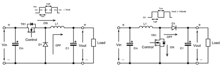
The first two switched-mode DC-DC converter types to be described are buck (step down) and boost (step-up) converters. Buck converters allow delivery of a DC output that is lower than the DC input. They can be utilised to provide different voltage rails so that sensitive electronic components are not exposed to voltages that could otherwise damage them. The switching mechanism within a buck converter will be turned on and off at high frequency, with energy being stored in an inductor enabling a smoothing of the output waveform.
At high power, multiphase buck converters can be used, so that component stresses are spread across a number of switches and inductors. To raise efficiency, buck converters with synchronous rectification will be recommended (with the Schottky diode being swapped for low on-resistance MOSFET).
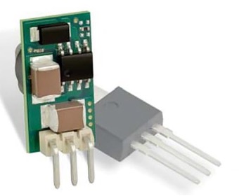
Attaining 83% efficiency, the Murata’s 78SR series is a popular non-isolated buck converter module, seeing strong uptake in embedded applications. It has a 7.5V to 36V input range and supports a 3.3V output at 0.5A.
In contrast to buck converters, boost converters allow the voltage output to be increased above the voltage input. This can be useful when looking to drive electric motors and suchlike. Normally boosts of 4-5 times greater than the input can be covered, but it is advisable not to go beyond that.
Providing Isolation
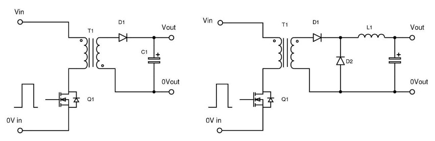
While simple buck and boost converters are adequate for many applications, they do not provide galvanic isolation - as their input and output grounds are connected. In situations where isolation is needed, with regard to medical equipment, for instance, such links need to be broken. That is where converters based on forward or flyback topologies come in. A flyback arrangement features a mutually coupled inductor with windings from the primary side and the secondary side of the circuit isolated from one another. Energy is stored in the inductor air gap during switching. A forward converter applies similar principles, but here an actual transformer is used to isolate the primary and secondary sides. Energy is directly transferred through the coil, rather than being stored within an inductor. This enables greater efficiency figures to be realised, though there can be disadvantages to this approach too. The most notable of these will be increased cost and lack of flexibility.
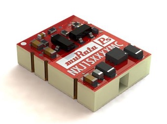
Targeted at medical applications, the 1W-rated Murata NXJ1 low-profile surface-mount converter modules each incorporate a substrate embedded transformer. They have been tested to ensure they can provide isolation up to 4.2kVDC voltages.
Streamlining DC-DC Converters by Eliminating Magnetic Elements
The inclusion of inductors or transformers is not necessary in non-isolated converters. Switched capacitor arrangements can be employed instead. Though switch and diode drops previously had an impact on efficiency, through synchronous rectification and the specifying of more advanced MOSFETs, elevated figures can now be derived. Leveraging a proprietary switched capacitor architecture, Murata’s Psemi technology can deliver efficiencies of above 96%. It is highly optimised for use in space-constrained telecom infrastructure.
So that concludes this blog on DC-DC conversion. Hopefully, it has given you some insight in the decisions that must be made when looking to source a converter module that is applicable to your particular application criteria. More:
Datasheet
Products