Hand soldering differs from reflow soldering in that the soldering process involves localized rapid heating of the desired point. During this process, it is necessary to be careful of the following two issues because of the characteristic temperature change and also residual stress.
-
In order to prevent damage (cracks) to the component that can be caused by localized rapid heating and heat shock, preheat the chip, for example, to prevent it from being subjected to heat shock.
-
The board temperature is lower than that used for reflow soldering, so a difference in residual stress occurs when the joint cools down, and the mechanical strength (resistance to bending) is liable to be low. In order to increase the strength, it is necessary to maintain the high temperature of the board during soldering.
If the board is single sided, you can carry out hand soldering while preheating the chip and the board using a hotplate. The following description, which applies to a two-sided board, covers 1 the method of soldering while preheating the parts of the board and the chip to be repaired using a spot heater, and 2 the method of soldering using a spot heater alone.
*Depending on the product series and part number, the mounting conditions may differ, or manual soldering may not be possible. please check the detailed specifications sheetDetailed specifications sheet
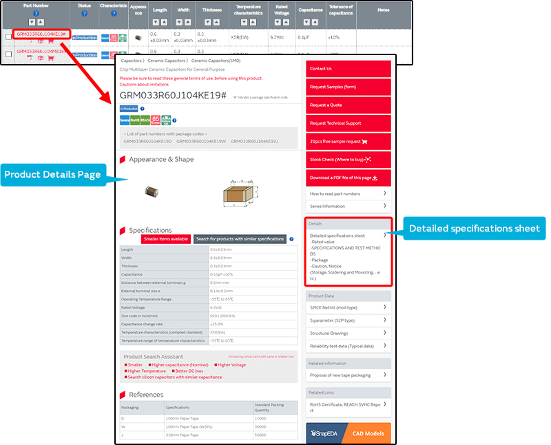 on our website.
1. Method of soldering while preheating the board and the chip with a spot heater
- Carry out preliminary soldering of the land on one side.
- Coat the tip and the land with flux.
- Preheat the chip with the hotplate.
- Apply hot air to the board to preheat it.
- When the chip and the board temperature reach the specified value, hold the chip with tweezers, and rapidly transfer it to the mounting position (the necessary preheating time will differ depending upon the thermal capacity of the board).
- Using a soldering iron, re-melt the preparatory solder, and solder the pins on one side.
- Solder the pins on the opposite side as well, while supplying reel solder.
2. Method of soldering using a spot heater alone
- Apply the preparatory solder to the land on one side.
- Coat the chip and the land with flux.
- Apply the spot heater and solder the pins on one side.
- Solder the pins on the opposite side as well, while supplying reel solder.
By carrying out soldering using a blast of hot air, it is possible to suppress the occurrence of cracks without preheating the chip. Also, when carrying out soldering work, it is possible to raise the soldering temperature of the board by applying a blast of hot air to the board.
Mechanism of the reduction of board bending resistance due to hand soldering
The greatest difference between the processes used for reflow soldering and hand soldering is the temperature of the board during soldering. This difference affects the board bending resistance.
During the cooling stage subsequent to soldering, the solder, chip, and board shrink. The shrinkage of the solder and chip is manifested as a tensile stress on the outer electrode terminal (stress concentration area), which is the point at which destruction of the chip starts to occur during the board bending resistance test. In contrast, the shrinkage of the board is manifested as a force in the compression direction, and mitigates other tensile stress. The compression stress from the board is determined by the board temperature when the solder starts to solidify.
In the case of reflow soldering, the entire joint is heated and cooled uniformly. In the case of hand soldering, on the other hand, the board temperature when the solder starts to solidify is low (between 50 and 70°C when preheating is not used), so the residual stress increases in the tensile direction applied to the stress concentration area when the board is cooled to normal temperature, and the board bending resistance falls below that of the case of reflow soldering.
Diagram showing estimation of stress generated during cooling shrinkage