External drive type piezoelectric sounder or a piezoelectric diaphragm emits sound when an AC voltage is applied to both terminals of the product.
Examples of typical drive circuits are broadly divided into case 1 where a transistor circuit is used and case 2 where the product is driven directly from a microcomputer.
Case 1: Transistor Circuit
Example of a drive circuit for a piezoelectric sounder and a piezoelectric diaphragm (external drive type) in the case where a transistor circuit is used
The higher the value of the voltage applied to V, the higher becomes the sound pressure of the piezoelectric sound component. Consequently, this drive method is widely used in cases where a power supply voltage that is higher than the drive voltage for the microcomputer can be obtained.
Please refer to the following supplementary notes regarding the components shown in the circuit diagram.
- Rp in the diagram is necessary for discharging the charge accumulated in the piezoelectric sound component, so be sure to use it. (Note: Approx. 680Ω to 1kΩ would be preferable.)
Also, if necessary, use Rs for volume adjustment.
- The transistor functions as a buffer for protecting the IC from back electromotive force generated by the piezoelectric sound component. Also, in order to protect the transistor itself, consider connecting a Zener diode in parallel with the piezoelectric sound component and Rp if necessary.
- A FET can be used instead of the transistor.
Case 2: Driven directly from a microcomputer.
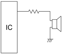
Example of a drive circuit for a piezoelectric sounder or a piezoelectric diaphragm in the case
where the sounder or diaphragm is driven directly from a microcomputer
A piezoelectric sound component has high impedance and is a voltage-driven device, so it can be driven directly from an IC, though, in order to make sound stable and protect IC, please add a resistor in series between IC output and sound component.
Please refer to the following supplementary notes regarding the components shown in the circuit diagram.
- In order to protect the IC from back electromotive force generated by a piezoelectric sound component, consider connecting a Zener diode in parallel with the piezoelectric sound component and Rp if necessary.
- Design the circuit in such a way that a DC voltage is not applied to the piezoelectric sound component for a long period.
- Please choose a suitable resistor not to exceed the maximum current rating of IC output pin. (Note: Approx. 470 to 1kΩ would be preferable.)