Study on Piezoelectric Vibration Mode Control and its Applications to Lead-Free Piezoelectric Ceramics
Akira Ando, Tadahiro Minamikawa, Masahiko Kimura, Takuya Sawada, Hirozumi Ogawa, Akira Tsubouchi, Tsutomu Okada
This paper received the Award for Academic Achievements from the Ceramic Society of Japan based on a review of its accomplishments, and it contains results dating from several years ago. Although the original paper was written under a single author, because this paper was written to commemorate the award-winning paper of the Ceramic Society of Japan, it provides the names of the prominent members who were involved in this research.
Piezoelectric ceramics are widely used in resonance device applications such as signal processing filters and resonators, actuator and sounder applications where electrical signals are converted to mechanical displacement, vibrations, or sound, and sensor applications where mechanical impact or stress is converted to electrical signals. Control of the behavior of the elastic vibrational wave that propagates inside the piezoelectric body is important for this conversion of electrical signals and mechanical signals.
Certain designs for the poling structure and grain structure for piezoelectric ceramics enable the obtaining of distinctive characteristics that were not possible before. This paper presents an energy trapping phenomenon (phenomenon where elastic vibration is concentrated in the electrode region) based on the poling structure design of piezoelectric ceramics using ceramic double-layering technology.
Energy Trapping of Thickness Extension Mode by Poling Structure Design
The fundamental vibration mode and odd-number order harmonic modes of the thickness extension vibration are coupled with the even-number order harmonic modes of the thickness shear vibration. The fundamental wave mode (TE1 mode) of the thickness extension vibration is coupled with the second-order harmonic mode of the thickness shear vibration (TS2 mode) . Because the resonance frequencies of the TE1 mode and TS2 mode are close to each other, the wave number and frequency have a relationship (dispersion relationship) where they exert a strong effect on each other due to the difference in the elastic characteristics of the material. If the Poisson ratio in isotropic media is less than 1/3, the resonance frequency of TE1 mode will be less than the resonance frequency of TS2 mode, and so the TE1 frequency will drop as the wave number increases as shown in Fig. 1 (a) .
Piezoelectric ceramics such as lead titanate, which shows thermally stable characteristics, exhibit this dispersion relationship. The dashed line in Fig. 1 shows the change in frequency for the region that forms the electrode. Also, in Fig. 1, the wave numbers on the right side of the vertical axis are real numbers, and the wave numbers on the left side are imaginary numbers. An imaginary value for the wave number means that a vibrational wave is not propagated. Taking a look at the dispersion relationship of the electrode region (dashed line) and non-electrode region (solid line) for TE1 mode, there are no frequencies where the electrode region is a real number and where the non-electrode region becomes an imaginary number.
In other words, there are no frequency regions for the TE1 mode vibrational wave with conditions where the electrode region only is propagated, and the non-electrode region is not propagated. A TE1 mode resonator was manufactured as shown in Fig. 2, and the impedance resonance characteristics were measured (Fig. 3 (a)) . This shows that the multiple waves propagated through the non-electrode region and reflected at the element end are superimposed at the electrode.
On the other hand, the second-order harmonic mode (TE2 mode) of the thickness extension vibration where excitation occurs due to the double-layer structure shown in Fig. 4 couples with the odd-number order thickness shear mode, and it does not couple with the even-number order thickness shear mode. Therefore, the dispersion relationship of TE2 mode does not couple with the thickness shear mode TS4 mode which has the closest resonance frequency. As a result, this exhibits the inherent dispersion relationship of the elastic wave with the TE2 mode, that is, a dispersion relationship where the wave number increases as the frequency increases.
Figure 1 (b) shows the dispersion relationship for TE2 mode of lead titanate piezoelectric ceramics. In this case, TE2 mode and TS3 mode are coupled. This shows that the frequency of TE2 mode increases as the wave number increases. In TE2 mode, there is a frequency area where the wave number of the electrode region is a real number, and the wave number of the non-electrode region is an imaginary number (frequency area shown by in Fig. 1 (b)) .
In other words, the vibrational waves are propagated in the electrode region only for this frequency area. This phenomenon where vibrational waves are propagated in a specific region only is called an energy trapping phenomenon. The impedance frequency response for TE2 mode is shown in Fig. 3 (b) , and this indicates that excellent impedance resonance characteristics for a single mode resonance are obtained.
The development of resonators for thickness extension vibration mode having low loss (high Q values) and high thermal stability has been an issue for many years, but it is possible that this issue can be resolved by using the energy trapping phenomenon based on the poling structure design.
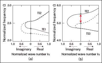
Fig. 1 Dispersion relationship of vibrational waves in TE1 mode (a) and TE2 mode (b)
The normalized frequency is given by , and half of the total resonator thickness is expressed as h.
The solid line and dashed line indicate the dispersion relationship of the vibrational wave propagating the non-electrode region and vibrational wave propagating the electrode region, respectively.
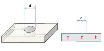
Fig. 2 Schematic view of a single-plate TE1 mode resonator
The arrows in the cross-sectional view indicate the poling direction of the piezoelectric ceramics.
The electrode diameter d is 1mm, and the total thickness of the resonator is 0.2mm.
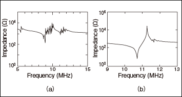
Fig. 3 Impedance resonance characteristics of TE1 mode resonator (a) and
TE2 mode resonator (b)
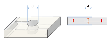
Fig. 4 Schematic view of TE2 mode resonator using double-layer structure
The arrows in the cross-sectional view indicate the poling direction of the piezoelectric ceramics.
The electrode diameter d is 1 mm, and the total thickness of the resonator is 0.2mm.
Application to Lead-Free Piezoelectric Ceramics
Next, this poling structure control technology was applied to lead-free piezoelectric ceramics. Generally, it is difficult to obtain lead-free piezoelectric ceramics that have a large piezoelectric constant, but it is also difficult to obtain lead-free piezoelectric ceramics that have superior resonance frequency temperature characteristics. Both cases require compositional phase boundaries, and this is because no other substances with compositional phase boundaries have been found besides lead-based piezoelectric ceramics.
We have conducted research and development on various types of lead-free piezoelectric ceramics, and we found that certain bismuth layer compound materials showed superior resonance frequency temperature characteristics irrespective of the compositional phase boundaries (see Table 1) .
The above-described poling structure design technology was applied to this material (SrBi2Nb22O9-based material) to achieve energy trapping and obtain practical resonance characteristics. The impedance resonance curve is shown in Fig. 5, and this shows desirable single-mode resonance characteristics.
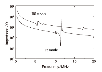
Fig. 5 Impedance resonance characteristics of SrBi2Nb22O9-based lead-free piezoelectric ceramics
Table 1 Properties of various types of lead-free piezoelectric ceramics
Conclusion: Future Materials Research and Development
The dispersion relationship that was presented in this paper was the relationship between the frequency and wave number, but if the frequency is generally taken as the amount corresponding to the energy, in terms of the solid-state physics theory, it can be considered to correspond to energy bands. We think that technology that achieves characteristics that were unobtainable before by controlling the structure in this way will take on growing importance in coming years.
We hope to utilize the recent innovations in nanotechnology for the microstructural design of substances and to control the energy bands to take on the challenge of creating new physical properties.
Original Paper: "Resonance characteristics derived by structural design of thermally stable piezoelectric ceramics," J. Ceram. So. Jpn. 118 pp.855-861, 2010