Chapter 1: What is a Power Inductor?
1.1 Overview of power inductors
A coil is a generic name for an electrode in the shape of a spiral. Among the different types of coils, there are coils called “inductors” which are used for electrical applications. Inductors can be further categorized into RF inductors used for signal processing, and power inductors for power supply lines. The power inductors discussed in this section form part of the voltage conversion circuit in a DC-DC converter or other device.
Here we will explain the operation of a power inductor in a DC-DC converter. A power inductor is used in a step-up, step-down, or step-up/step-down circuit to convert a certain voltage to the required voltage. Among those different circuits, it is primarily used in a type of circuit called a “switching regulator.”
Figure 1-1 shows an example of a switching regulator step-down circuit.
It uses an IC, power inductor, and capacitor to convert a DC input voltage to the required output voltage. The power inductor works with the capacitor to play the role of rectifying the rectangular wave output from the IC to a direct current (further details are explained in Chapter 2).
If either one of these components is missing, the output cannot be properly rectified.
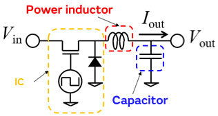
Figure 1-1 Overview of a step-down switching regulator
1.2 Basic characteristics of power inductors
Now what parameters should you pay attention to when selecting a power inductor? The power inductor catalogs of each manufacturer list the following principal specifications. Figure 1-2 shows an example of a specification table.
- Inductance
- Rated current
- DC superposition rated current Isat
- Temperature increase rated current Itemp
- DC resistance Rdc
- Operating temperature range
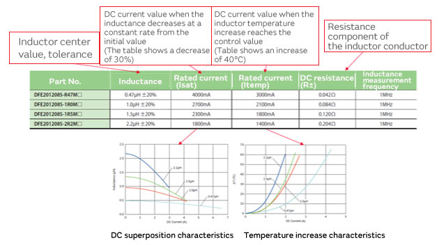
Figure 1-2 Power inductor characteristic table
However, we don’t know the right specification for which power inductor to choose with only this information. For example, questions such as whether a high or low inductance is better, or what rated current is required, must be considered to appropriately choose an inductor according to the operating conditions of the DC-DC converter. In this chapter, we will cover how to read power inductor specifications.
What is an Inductance?
The inductance value is an extremely important parameter which affects the ripple current and load response characteristics. As shown in Figure 1-3, an exponential current flows through a power inductor used in a DC-DC converter. Generally speaking, it is considered to be a good idea to set the ripple current ⊿IL to about 30% of the load current Iout. Therefore, once the DC-DC converter conditions are decided, you can calculate the proper power inductor inductance with the following equation.
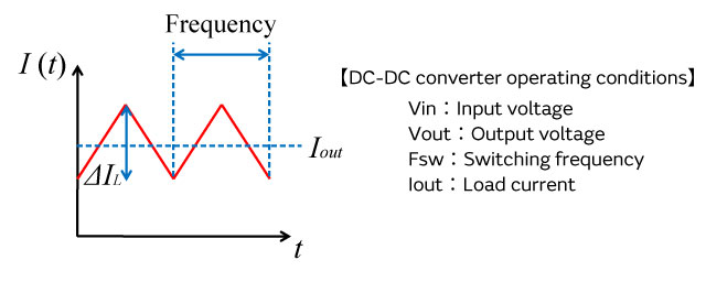
Figure 1-3 Current waveform flowing through a power inductor
However, most DC-DC converters list the proper inductance value as a reference. Therefore, you can also follow the manufacturer reference to select the power inductor without calculating the formula above.
Rated current
The rated current stipulates the current value at which the quality can no longer be guaranteed once the DC current exceeds it. The rated current of a power inductor stipulates a value for the DC superposition rated current (Saturation) and a value for the temperature increase rated current (Temperature). The meaning of each value is important, so in many cases they are listed as separate specifications.
ⅰ)DC superposition rated current Isat
One characteristic of an inductor is the DC superposition characteristic. To obtain a high inductance, ferrite and other magnetic materials are used in the core (magnetic core) of the inductor. When a current flows through the inductor, the phenomenon called the magnetic saturation of the magnetic substance occurs, and the inductance decreases. This characteristic is called “DC superposition.” The DC superposition rated current stipulates the current value when this inductance decreases at a constant rate with regard to the initial characteristic that the current is not superimposed on.
ⅱ)Temperature increase rated current Itemp
This is the rated current requirement which uses component heat generation as an index and use beyond this range will lead to component and set damage. Typically, it is defined as the current value where the temperature increase is ⊿40°C.
Now let’s look at how to determine these rated currents when used as a power inductor. As shown in Figure 1-3, the maximum current which flows through the inductor is Iout + ⊿IL/2. When this current value exceeds Isat, the decrease in inductance becomes quite large; the shape of the exponential current becomes abnormal as shown by the red line in Figure 1-4, and the ripple current increases. Because the ripple current causes the output voltage to fluctuate, it induces abnormal system behavior on the load side when the ripple current increases. Therefore, you must choose a power inductor with an Isat that is greater than the maximum current.
At the same time, with regard to the temperature increase rated current, the inductor is not immediately damaged even if the rated value is exceeded. Accordingly, you should select an Itemp value which is greater than Iout as a general rule.
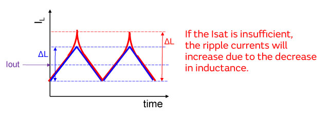
Figure 1-4 Ripple current fluctuations due to the DC superposition
DC resistance Rdc
The DC resistance is the resistance value when the direct current flows. Because power loss occurs through heat generation due to this resistance value, a lower DC resistance can reduce loss. However, reducing the Rdc involves a trade-off between the DC superposition characteristic and size miniaturization. Therefore, it is probably better to select an inductor with a smaller Rdc from among those inductors which satisfy the necessary characteristics such as inductance and the rated currents discussed above.
Operating temperature range
The operating temperature range stipulates the allowable range of ambient temperature when using an inductor. The effect of temperature can change even based on the circuit operating environment, so please select an inductor based on the expected practical use environment.
Now let’s take a look at an example of selecting a power inductor in an actual DC-DC converter. This example is based on the step-down DC-DC converter shown in Figure 1-5. It is expected to operate under the following conditions:
[Operating conditions]
- Vin
- 3.6V
- Vout
- 1.8V
- FSW
- 2.0MHz
- Iout
- 1.5A
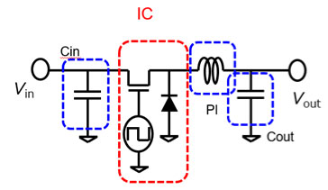
Figure 1-5 Step-down DC-DC converter example
With the following equation, we see that the magnitude of the proper inductance is about 1.0 μH.
Moreover, because Iout = 1.5 A and ⊿IL is 0.45 A at about 30% of Iout, the maximum current is as follows:
Iout+⊿IL/2=1.725A
Therefore, based on this result, we need an inductor with an Itemp of 1.5 A or more and an Isat of 1.8 A or more.
By using Murata’s design support software called the “SimSurfing / DC-DC Converter Design Support Tool,” you can search for the ideal item based on the required specification. For example, when the required values for inductance, size, Itemp, and Isat are entered from among the search items shown within the red frame in Figure 1-6, the items which match the conditions are listed within the blue frame.
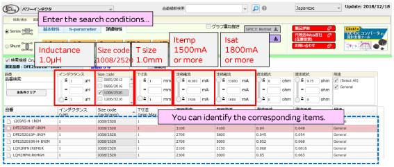
Figure 1-6 Search conditions in the “SimSurfing” design support software
You can also compare basic characteristics such as the DC superposition characteristic by selecting items.
In Figure 1-7, the following three items are selected to compare the superposition characteristic:
DFE252010F-1R0M
LQH2HPN1R0MGR
LQM2HPN1R0MGH
Based on these results, for this example, we can see that the DFE252012P-1R0M satisfies the required conditions and possesses low Rdc and high Isat characteristics.
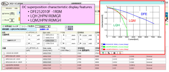
Figure 1-7 Comparison of basic characteristics with the “SimSurfing” design support software
1.3 Types of power inductors
Starting from here, we will introduce the different types of power inductors. The Murata lineup includes power inductors with winding Metal Alloy, winding ferrite, and multilayer ferrite structures. We provide the optimal inductors for a wide range of applications from mobile devices such as wearables and smartphones to medical, industrial electronics, and automotive equipment.
Figure 1-8 Power inductors structures
Let’s take a look at the advantages and technologies behind each structure.
Winding Metal Alloy
Winding Metal Alloy is an inductor which bonds the winding and resin-coated metal magnetic powder with thermocompression. It can be applied to high current areas in large-sized to small-sized products. While metal magnetic materials have a lower magnetic permeability when compared to the ferrite materials described below, they have superior DC superposition characteristics, so they are materials which are well-suited to high currents. As DC-DC converters have shifted toward high-speed switching in recent years, low inductance is required, so winding Metal Alloy is becoming a leading product in the majority of the market.
Moreover, the superior temperature characteristics compared to ferrite materials are also a major advantage. Because the fluctuations in magnetic permeability are small with regard to the ambient temperature, it can maintain stable DC superposition characteristics even at high temperatures. The wide-ranging target markets include automobiles, smartphones, HDDs, etc.
Figure 1-9 Structure and appearance of winding Metal Alloy
Winding Metal Alloy technologies include metal magnetic materials and their processing techniques as well as winding techniques using copper wire (Figure 1-10). At Murata, we have established material technologies which realize our own winding structure, high magnetic permeability, and insulation. By combining these technologies, we have improved the efficiency of achieving inductance, enabled low DC resistance, and created a product lineup which supports high currents.
Figure 1-10 Cross-sectional view of winding Metal Alloy
Winding Ferrite
Winding ferrite: winds copper wire in a spiral shape around a ferrite core. Many of Murata’s winding ferrite products coat the copper wire, wound around the ferrite core, with a magnetic resin. The purpose of the resin coating is to reduce the leakage flux, improve the achievement of inductance, and increase the intensity. Because the magnetic permeability of ferrite material is high, there are advantages to selecting winding ferrite when using it in a high inductance area. The wide-ranging target markets include smartphones, TVs, HDDs, etc.
LQH_P series
LQH2MC_02 series
LQH2MC_52 series
Figure 1-11 Structure and appearance of winding ferrite
Figure 1-12 Cross-sectional view of winding ferrite
Multilayer Ferrite
Multilayer ferrite is an inductor which alternately laminates and sinters the magnetic material and inner electrodes. Compared to the winding structure, it enables compact and low-profile form factors. While the cases where winding Metal Alloy is used to satisfy the demand for small size and low inductance have been increasing, the characteristics of multilayer ferrite will be needed in areas requiring a small size with a high inductance and high voltage.
LQM_F series
LQM_P series
Figure 1-13 Structure and appearance of multilayer ferrite
Multilayer ferrite technologies include ferrite material technology and technology for forming inner electrodes with a high aspect ratio, circuit design technology, and lamination technology (Figure 1-14). Murata has obtained high aspect technology for inner electrodes, which was not achievable with previous sheet lamination that enables us to provide even lower resistance. In addition, the magnetic path gap forming technology with a high degree of freedom suppresses magnetic saturation to achieve a vastly superior DC superposition characteristic. These technologies realize a product lineup which supports areas that require a compact and low-profile form factor.
Figure 1-14 Cross-sectional view of multilayer ferrite
Next, let’s compare the performance of these power inductor structures.
Performance comparison of power inductors
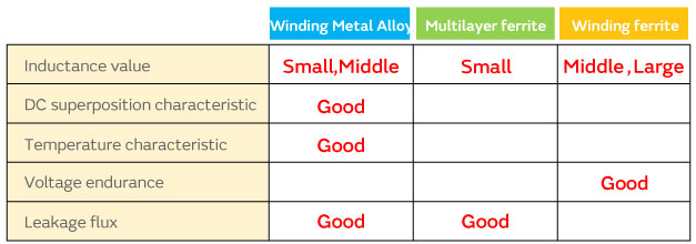
The primary factors for comparing power inductor performance are the 1) inductance value, 2) DC superposition characteristic, 3) temperature characteristic, 4) voltage endurance, and 5) leakage flux. Knowing these factors will enable you to select the power inductor structure which is suited to the required level of performance.
1) Inductance value
The range of obtainable inductance values is determined by the structure of the inductor. Winding ferrite can obtain a wide range starting from ferrite materials with a high magnetic permeability up to a high inductance of 10 uH or more. Due to the fact that multilayer ferrite is more compact when compared to winding ferrite, it achieves a low inductance of 10 uH or less. Winding Metal Alloy is noted for its low inductance of 10 uH or less due to its material characteristics.
Figure 1-15 Range of inductance by structure
2) DC superposition characteristic
A circuit which conducts a high current, such as a digital circuit, requires a power inductor with an inductance that does not decrease due to a high current, that is to say, a power inductor with a good DC superposition characteristic. This means that because the inductance does not decrease, the ripple currents are kept constant, and stable circuit operation can be maintained. In the case of winding Metal Alloy, because it is difficult for magnetic saturation to occur in comparison to ferrite, it possesses a superior DC superposition characteristic.
Figure 1-16 Superposition characteristic by structure
3) Temperature characteristic
When power inductors are used under high temperatures, such as in the power supply circuit of an automobile, the temperature characteristic becomes extremely important. Within magnetic materials, there is a temperature characteristic whereby the magnetic permeability changes according to the temperature, but metal magnetic materials have smaller changes in magnetic permeability due to temperature than ferrite materials and can be said to have superior characteristics.
In the case of winding Metal Alloy, there are no significant changes in the inductance value or the DC superposition characteristic. Figure 1-17 shows the DC superposition characteristics of winding Metal Alloy and ferrite products across a range of ambient temperatures from 25°C to 125°C. We can see that characteristic of winding Metal Alloy is unchanged between 25°C and 125°C.
Figure 1-17 Temperature characteristic by structure
4) Voltage endurance
It is important to pay attention to the power inductor voltage endurance in an LED or other voltage boosting circuit and power supply circuits with a high step-down voltage ratio. In the case of winding Metal Alloy, it ensures the insulation by covering the metal magnetic powder with an insulating resin, but the insulation tends to be lower when compared to winding ferrite. For this reason, while winding Metal Alloy possesses many superior characteristics, confirmation is required when using it in a high voltage endurance situation.
5) Leakage flux
The leakage flux from an inductor affects other circuits as noise which can lead to problems such as signal degradation and malfunctions particularly in power supply circuits with restrictions on the distance between components. The magnitude of the leakage flux is highly dependent on the structure of the inductor, and the closed magnetic circuit structures of the winding Metal Alloy and multilayer ferrite are helpful in this regard. This is because the winding Metal Alloy and multilayer ferrite enable you to reduce the leakage flux to the outside when trying to obtain the same inductance (Figure 1-18). The comparison results for leakage flux by structure are shown in Figure 1-19. From the results, we can see that the winding Metal Alloy and multilayer ferrite are able to suppress the leakage flux to low levels compared to the winding ferrite.
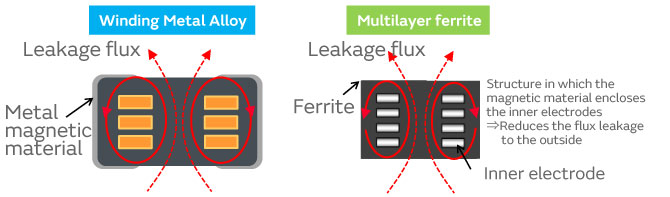
Figure 1-18 Cross-sectional views of winding Metal Alloy and multilayer ferrite
Figure 1-19 Leakage flux by structure
Table 1 summarizes the performance comparison. When selecting a power inductor, please refer to this table to select the inductor which is best suited to your application.
Table 1 Performance comparison by structure
Finally, we will introduce our lineup of recommended power inductors. Power inductor applications can be broadly categorized into general use and automotive use applications.
Winding Metal Alloy can take on a wide range of inductance values and sizes. Winding ferrite possesses an advantage as a high inductance product while the strength of multilayer ferrite lies in its compact size.
1.4 Power inductor selection issues
In Chapters 1.1 through 1.3, we explained how to look at the various power inductor characteristics and the differences in features due to the construction methods. However, we believe that what designers are most concerned about are not the power inductor characteristics but the performance when it is used in a DC-DC converter.
Figure 1-21 shows the efficiency measurement results for winding Metal Alloy and multilayer ferrite inductors with the same size and inductance values in a DC-DC converter. We can see in Figure 1-21 that the efficiency significantly differs by roughly 3% depending on the type of component.
However, regrettably this difference cannot be interpreted from the current specification being described. Selecting a product based on the actual performance requires a deeper understanding of power inductor characteristics and an evaluation based on the operating conditions of the DC-DC converter.
Accordingly, the next chapter will explain the operating principles of a DC-DC converter and the relationship between the performance of a DC-DC converter and the power inductor specification. It will also provide an example of how to evaluate the actual performance of a power inductor in a DC-DC converter using the Murata DC-DC Converter Design Support Tool.
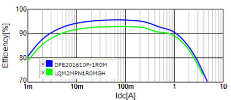
Figure 1-21 Winding Metal Alloy and multilayer ferrite efficiency measurement results