Innovation in Technological Development Realizes High-Performance Surface Acoustic Wave Devices
Communications terminals are equipped with radio frequency filters, or RF filters, which process signals over a range of 800 MHz to 2500 MHz. Filters using a surface acoustic wave, or SAW, which propagates along the surface of a piezoelectric substrate, have been thus far widely used in these RF filters, but in recent years, following the increasing commercial application of a bulk acoustic wave, or BAW, the application of filters using BAW to the highly difficult bands that traditional SAW filters cannot deal with has increased.
Murata has developed Incredible High Performance-SAW filters, or I.H.P. SAW filters, which have overcome the shortcomings of traditional SAW filters, and successfully accomplished characteristics superior to BAW filters. In this article, we introduce the technologies used in the I.H.P. SAW filters.
1. Present State of RF Filters and Challenges in SAW Filters
RF filters are used in the transmitter and receiver circuit, or transceiver circuit, of communications terminals. They are devices that allow the passage of signals of desired frequency bands and block the passage of other unwanted ones. They are composed of more than one resonator: In general, a desired filter bandwidth is tailored by ladder circuits that are composed of resonators connected like a ladder (Fig. 1) . Bands available for communications terminals include those with various frequencies and passband bandwidths. The designs of the circuits and resonators in the terminals are optimized to comply with the standards of each allocated band.
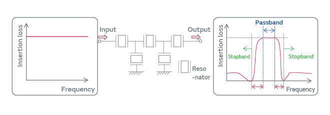
Fig. 1. Schematic diagram of an RF filter (ladder circuit)
What is important in the RF filters is steepness of the transition band, which is the curve connecting the passband and the stopband in the filter bandpass characteristics. The RF filters of which bandwidth between the passband and the stopband, or their transition bandwidth (as indicated by red arrows in Fig. 1) , is narrow are hard to design; filter characteristics with steeper transition bands are necessary. To increase the steepness of the transition band, the circuit design of the resonators composing the filters is certainly important; but the characteristics of the resonators themselves (quality factor, or Q factor) are also very important. To cater to the demand for the filter design for these highly difficult bands, various makers have been working to improve the Q factor of the resonators.
SAW devices based on monocrystalline piezoelectric LiTaO3 substrates have been widely used in RF filters. The filters have interdigital transducers, or IDTs, which are comb-shaped electrodes, mounted on the surface of a piezoelectric substrate. The resonance characteristics of the surface acoustic wave excited by the IDT is responsible for the characteristic band of the RF filter (Fig. 2) .
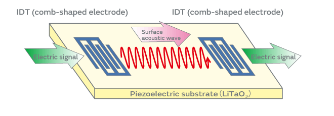
Fig. 2. Surface acoustic wave device
There is a competing RF filter technology against SAW, which uses a bulk acoustic wave, or BAW. Common BAW filters have a piezoelectric substrate sandwiched between two electrodes and use thickness expansion vibration. The BAW filters, although characterized by the complexity in the manufacturing process and their high production cost, can accomplish higher Q characteristics than the SAW filters. The resonance characteristics of BAW allow us to construct RF filters that can achieve superior filter characteristics with a higher steepness. There are some technological challenges in terms of heat dissipation in the SAW filters; hence, the BAW filters have dominated the market of products for the highly difficult bands.
In this kind of environment, Murata has successfully developed the I.H.P. SAW filters, which have overcome the shortcomings of traditional SAW filters. The I.H.P. SAW filters provide a higher additional value; that is, while the products can offer filter characteristics equivalent or superior to the BAW filters, they possess temperature characteristics superior to the BAW filters: They have an advantage of higher heat dissipation.
2. Characteristic Features of the I.H.P. SAW Filters
The I.H.P. SAW filters are surface acoustic wave devices characterized by (1) high Q factor, (2) low temperature coefficient of frequency, or TCF, and (3) high heat dissipation.
(1) High Q Factor
The I.H.P. SAW filters can realize high Q factor characteristics. The filters adopt a structure that makes the energy of surface acoustic waves focus on the surface of the substrate, allowing the lossless propagation of the wave over the substrate. The peak value of the Q characteristics, or Qmax, of a resonator prototype exceeded 3,000 at the 1.9 GHz band, which was a substantial improvement as compared with traditional SAW filters, of which Qmax is typically about 1,000.
Figure 3 shows an instance of the I.H.P. SAW application to an RF filter. The targeted band is band 25, a band that has been considered the most difficult to deal with. Satisfactory characteristics were obtained in the actual measurements: The typical values of the insertion loss were Tx: 1.5 dB and Rx: 2.1 dB, and the typical values of the isolation were TxIso: 57 dB and RxIso: 59 dB. The results indicate an applicability of this new filter to the highly difficult band 25.
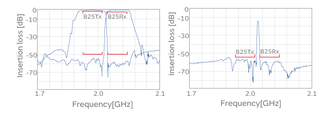
Fig. 3. The I.H.P. SAW Band25DPX (left: transmission characteristics, right: isolation characteristics)
(2) Low TCF
The I.H.P. SAW filters can improve frequency-temperature characteristics. The filters accomplish satisfactory temperature characteristics by simultaneously controlling the linear expansion coefficient of the substrate and the speed of sound. Figure 4 shows the filter characteristics when the temperature was changed from -35°C to +85°C. Traditional SAW filters exhibit a very large shift of about -40 ppm/°C in TCF, whereas the I.H.P. SAW filters can exhibit an improved shift of ±8 ppm/°C or less. This improvement of TCF by about 30 ppm/°C can further be improved to 0 ppm/°C by appropriately designing the structure of the substrate.
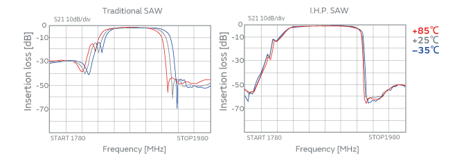
Fig. 4. Filter waveform under the variation of temperature (blue: -35°C, black: +25°C, red: +85°C)
The TCF of the I.H.P. SAW filters is better than that of the BAW filters. The TCF of common BAW filters is in the range of -20 to 30 ppm/°C. So, the I.H.P. SAW filters realize better temperature characteristics than the BAW filters in terms of the TCF. The low TCF characteristic features of the I.H.P. SAW filters will be a huge advantage in designing the filters in the recent trend of even stricter demand for better temperature characteristics.
(3) High Heat Dissipation
The I.H.P. SAW filters exhibit a satisfactory heat dissipation. When there is an input of high power electric signal, the IDT generates heat. The input of more intense signal generates further heat, which may cause a malfunction of devices, including the breakdown of electrodes. The I.H.P. SAW filters can dissipate the heat generated at the electrodes efficiently onto the substrate, which helps reduce an increase in temperature upon startup to less than half of that by traditional SAW filters. The combined effect of low TCF and high heat dissipation stabilizes the response of the filters at high operating temperature.
3. Future Potential
The I.H.P. SAW filters can exhibit satisfactory characteristics over a wide range of frequency spectrum from lower frequency (800 MHz band) to higher frequency (2500 MHz band) . In recent development, satisfactory results were obtained for the frequency characteristics in the 3.5 GHz band, which had been considered difficult with traditional SAW filters (the peak value at 3.5 GHz in Fig. 5) . The evolution of mobile terminals to further high-speed communications tools is an inevitable path in the future. The I.H.P. SAW filters are products that can be adapted for the challenges to be posed by next-generation communications terminals.
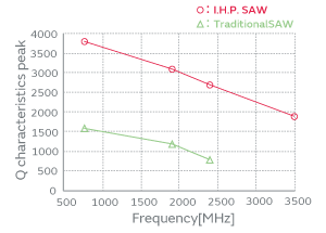
Fig. 5.Q characteristics comparison of the I.H.P. SAW and traditional SAW filters
One of the characteristic features of the I.H.P. SAW filters is the degree of freedom in the adjustment of fractional bandwidth. The I.H.P. SAW filters allow filter engineers to choose any fractional bandwidth they like. A band may have a variety of bandwidth from narrow band to broad band. The I.H.P. SAW filters help filter engineers design filters that are optimized for various bands by allowing them to choose desired bands.
Additionally, the I.H.P. SAW filters can be adapted for the requirement of filter miniaturization. The above-mentioned three characteristic features will facilitate substantial miniaturization of the devices as compared with traditional SAW filters. The demand for the miniaturization of filters is expected to be strengthened in the future as the downsizing of mobile terminals advances. In this kind of environment, the I.H.P. SAW filters are ideal products that can provide an advantage in size.
4. Conclusion
The I.H.P. SAW filters offer excellent additional values: The devices provide better characteristics than BAW filters, while using a technology of surface acoustic waves. The requirements for the RF filters are expected to become increasingly severe year by year, reflecting the demand for frequency expansion, further miniaturization, multiband implementation, etc. In this kind of environment, we expect to encounter an increasing number of situations in the future to which only the I.H.P. SAW filters can provide solutions. We do hope that the I.H.P. SAW filters will be core marketing products in Murata’s RF component lineups, and we will devote ourselves to providing our clients with our stable quality products.
Glossary
SAW (Surface Acoustic Wave) filter:
A filter that can pick out electric signals in a particular frequency band, using the surface acoustic wave that propagates along the surface of the piezoelectric substrate.
BAW (Bulk Acoustic Wave) filter:
A filter that can pick out electric signals in a particular frequency band, using the vibration of the bulk of the piezoelectric substrate.
Band:
A frequency band that can be used for communications. The frequencies and the bandwidth vary by country or region.
Q Factor (Quality Factor) :
An indicator that expresses the sharpness of the resonance peak. The greater the Q factor, the smaller the loss in the filter, which is better for filter characteristics.
TCF (Temperature Coefficient of Frequency) :
The coefficient indicates the corresponding variation of frequency against the variation of temperature. The smaller the TCF, the more stable the device is against temperature variation.