Chapter 2: What is a DC-DC Converter?
Chapter 1 explained how to view the characteristics of power inductors and their different features based on their structure.
A power inductor is a functional part that consists of DC-DC converters and other voltage shifting circuits, and so their specific advantages and disadvantages and the selection of constants must be based on the operation mechanism of the DC-DC converter. This chapter describes the operation mechanism of DC-DC converters and the role of power inductors.
2.1 Overview of DC-DC converters
DC-DC converter is a collective term for circuits that convert an input voltage in a certain range to a fixed output voltage.The types of DC-DC converters are linear regulator and switching regulator. The circuit configuration also varies depending on whether the input voltage is stepped down or stepped up, and these include a wide range of types.
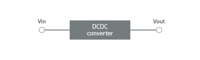
Figure 2-1 Definition of DC-DC converter
2.2 Need for DC-DC converters
DC-DC converters are needed for power supply circuits only. The CPU, memory, LEDs, and other devices require many different DC voltages to run. However, in the lithium-ion batteries used in mobile devices, for example, the battery voltage (power supply) outputs about 3.7 V only. DC-DC converters are needed for adjusting these differences in voltages. DC-DC converters are required in most electronic devices, and typically, a large number of them are used in a device.
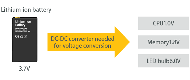
Figure 2-2 Need for DC-DC converters
2.3 Classification of DC-DC converters
DC-DC converters can be classified as linear regulators or switching regulators.
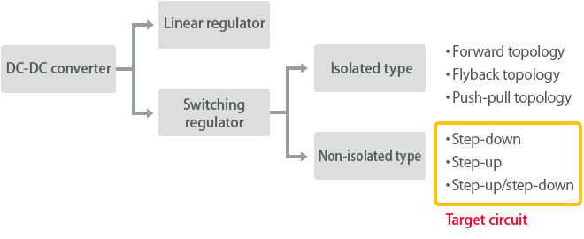
Figure 2-3 Classification of DC-DC converters
2.3.1 Principles of linear regulators
A linear regulator is the simplest conversion method, and the voltage is converted by voltage division using resistors. For example, to set half of an input voltage as the output voltage, an equal load resistance and regulator variable resistance are used to divide the input voltage by one-half.
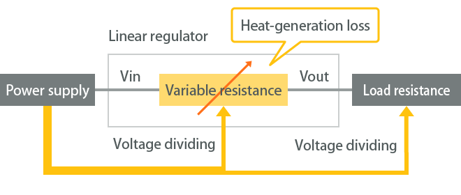
Figure 2-3-1 Principles of linear regulators
While this method is simple and low-cost, one drawback is that it uses resistors, and larger potential differences for the input/output result in higher power losses (lower efficiency). Consequently, this reduces the battery runtime for mobile devices. Furthermore, a cooling mechanism is sometimes installed for the purpose of reducing the heat generated by the power losses. For this reason, linear regulators are commonly used when the power used is small or when the input/output potential difference is small. Switching regulators (explained next) are used in most circuits with a relatively higher power usage.
2.3.2 Principles of switching regulators
The switching regulator consists of a circuit combining switching elements, inductors, capacitors, and other functional parts. The switch is turned ON or OFF at high speed to enable adjustment of the output voltage, and ideally, the voltage is converted without any power loss.
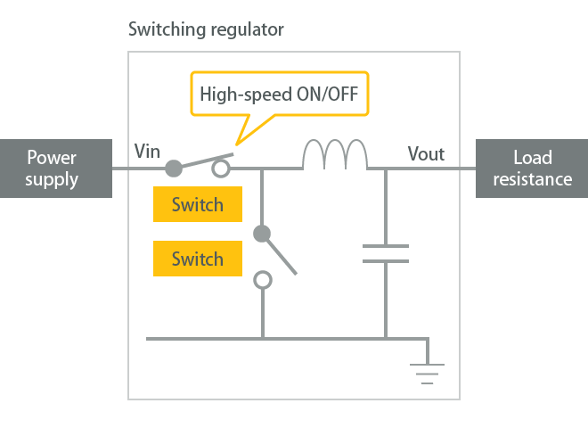
Figure 2-3-2 Principles of switching regulators
This method is further divided into isolated and non-isolated types. The isolated-type switching regulator is a method where the input voltage (primary side) and output voltage (secondary side) are isolated by a transformer. This is used to prevent electric shock and electric leakage when converting high-voltage circuits. In contrast to the isolated type, the non-isolated type is a method where a transformer is not used, and the input and output are not isolated. Most mobile devices and in-car devices using batteries use non-isolated DC-DC converters because of their low voltage.
2.4 DC-DC converter usage examples
This section presents examples of non-isolated DC-DC converters that are actually used in smartphones and automobiles.
2.4.1 Usage example: Smartphone
A smartphone uses DC-DC converters in the following locations.
We will examine specific examples of a power supply for digital circuits, power supply for RF circuits, and power supply for display circuits.
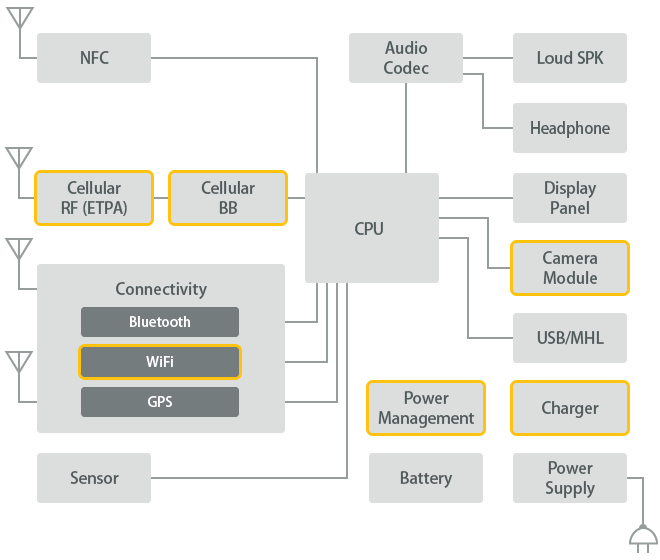
Figure 2-4-1 DC-DC converter installation locations in smartphone
1) Power supply for digital circuits(PMIC*1)
Digital circuits primarily refer to CPU, GPU, memory, and similar circuits. Digital circuits are characterized by a driving voltage of about 0.8 V to 1.8 V, which is lower than the battery voltage of 3.6 V to 3.8 V. For this reason, step-down DC-DC converters are needed. The DC-DC converters used for digital circuits are characterized by a high-speed switching frequency and large output current. The power inductors that are used here are compact and have a low L inductance value (L=about 1 uH).
*1) PMIC: Power Management IC. This is an IC where multiple DC-DC converters and control microcontrollers are installed for multifunctional LSIs that require DC-DC converters with multiple channels.
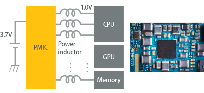
Figure 2-4-1-1 Example of usage in digital circuit
2) Power supply for RF circuits
Following digital circuits, DC-DC converters are next most commonly used in RF circuits. The RF circuits that incorporate DC-DC converters are primarily envelope tracking ICs (ET ICs), baseband processors, Bluetooth modules, Wifi modules, and similar. Because these components run on a lower voltage than the battery, step-down DC-DC converters are needed. The DC-DC converters used for RF circuits are characterized by modular designs where power inductors and capacitors are already installed inside (L=about 2.2 uH).
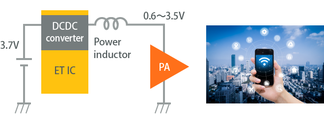
Figure 2-4-1-2 Example of usage in RF circuit
3) Power supply for display circuits
DC-DC converters are also used in smartphone displays. Because the organic EL displays and LED backlight used in LCD screens require a voltage higher than the battery, step-up DC-DC converters are used. In LED backlights, the output voltage is adjusted based on the number of lights. The DC-DC converters used for display circuits are characterized by the use of high voltage-resistant switching elements, and so it is difficult to set a high switching frequency. For this reason, power inductors with a high L inductance value are used (L=about 10 uH).
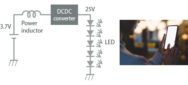
Figure 2-4-1-3 Example of usage in display circuit
2.4.2 Usage example: Automotive
Automobiles also use a large number of non-isolated DC-DC converters. Automobile applications are roughly divided into the following classifications.
For power trains and safety devices, use of a DC-DC converter with one output is relatively common, but in infotainment, a PMIC is also used. One of the main differences from smartphones is that the operating voltages can become large, such as input voltages of 12 V or 48 V in the DC-DC converter. Because of the broad range of applications, the inductance value varies widely depending on the application where it is used.
Main applications where power inductors are used
- Powertrain
- Safety
- Infotainment
- Comfort
- xEV System
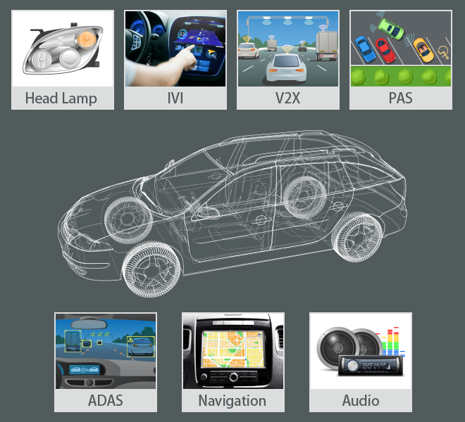
Figure 2-4-2-1 DC-DC converter installation locations in automobile
Let's take a look at the ADAS used for safety devices, head lamps, and the IVI used for infotainment.
1) Power supply for ADAS and IVI
In ADAS and IVI, the voltages required for running applications are lower than the battery, and so a step-down DC-DC converter is used. The configuration is remarkably similar to the power supply configuration used in smartphones and PCs. Some examples of applications are cameras and sensing for ADAS and audio for IVI. The DC-DC converters for ADAS and IVI are typically characterized by a configuration with primary and secondary step-down circuits where the voltage steps down from 12 V to the range of 3.3 V to 5.0 V, and then steps down again for each application.
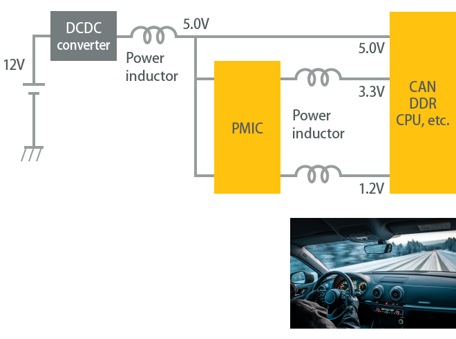
Figure 2-4-2-2 Example of usage in ADAS and IVI
2) Power supply for head lamps
In head lamps, step-up DC-DC converters are primarily used for LED lighting. The output voltage is adjusted based on the number of lights. The DC-DC converters for head lamps are characterized by the use of power inductors with large inductance values similar to those in LED backlights for smartphones.
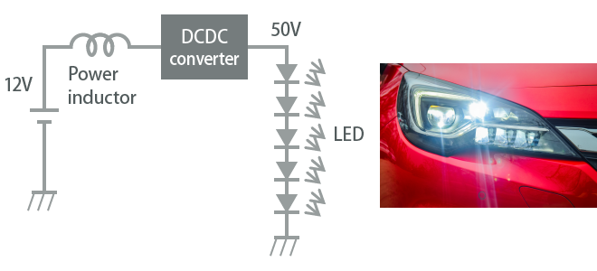
Figure 2-4-2-3 Example of usage in head lamp
2.5 Operating principles of DC-DC converters
This section will describe the operation mechanism for non-isolated switching regulators. The structures of DC-DC converters are step-down, step-up, and step-up/step-down types. This section will describe the operation mechanism using a step-down switching regulator as an example.
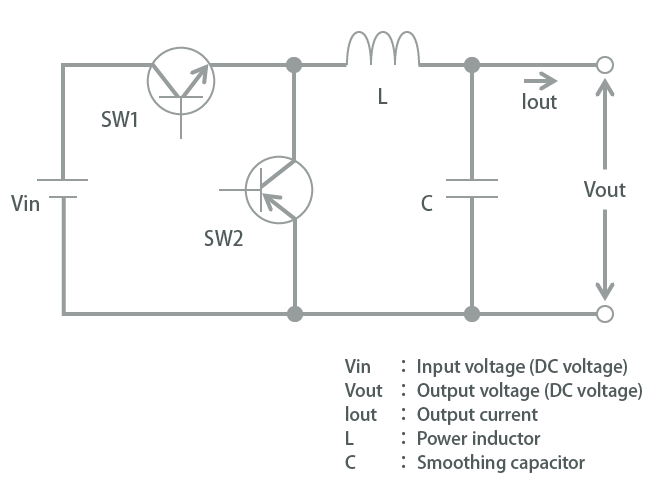
Figure 2-5-1 Basic diagram of step-down DC-DC converter
The basic circuit diagram for a step-down switching regulator is shown in Figure 2-5-1. One power inductor is installed in the circuit. This operates so that, when SW1 turns ON, SW2 turns OFF, and when SW1 turns OFF, SW2 turns ON. The changes in the circuit when the switch changes to ON or OFF are shown in Figure 2-5-2. The location of the input-side terminal of the power inductor is point A.
When SW1 turns ON and SW2 turns OFF, the voltage from the input power supply is supplied directly to the power inductor, and the electric potential of point A becomes equal to Vin. Next, when SW1 turns OFF and SW2 turns ON, the power inductor is isolated from the input power supply and is connected to the GND. As a result, the electric potential of point A becomes equal to GND.
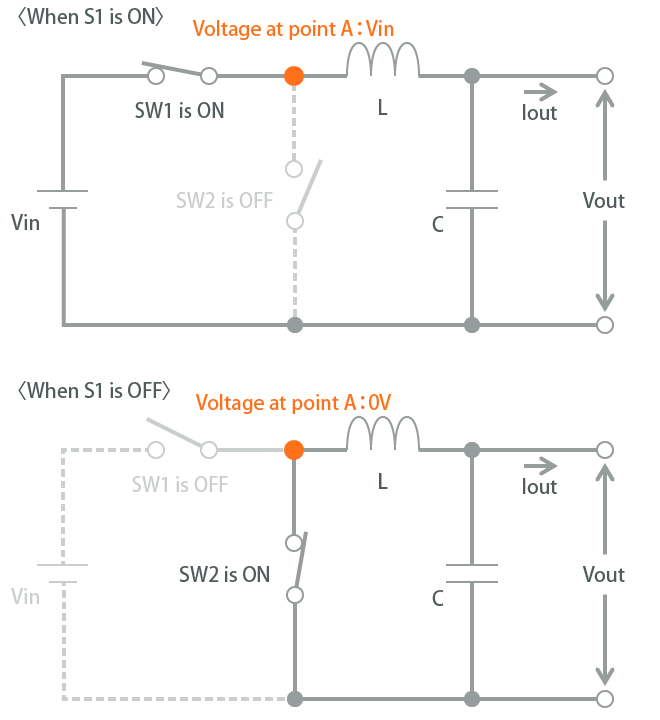
Figure 2-5-2 Operating principles at switch ON/OFF
These two states are repeated by the switching operation so that the input-side (point A) voltage of the power inductor repeatedly alternates between the two values of Vin (V) and 0 (V). For this reason, a pulse voltage of an amplitude Vin is applied to the input side of the power inductor.
How then does the power inductor function so that a fixed voltage is supplied to the output side? Let's focus on the power inductor and smoothing capacitor making up the LC low-pass filter circuit. We can see that the pulse voltage supplied from the input side is smoothed and output by the LC circuit. When we look at it this way, the mechanism that outputs a fixed voltage is easy to understand.
Figure 2-5-3 shows the relationship between the point A voltage and Vout during the switching operation. The upper figure shows the case when the SW1 ON time is 50% overall, that is, the duty ratio is 50%. The voltage in this stage is smoothed so that the 50% of Vin (Vin/2) is output as the output voltage Vout. The lower figure shows the case when the duty ratio is 25%. The 25% of Vin (Vin/4) is output as the output voltage Vout.In other words, when the output voltage is high, the duty ratio becomes higher, and when the output voltage is low, the duty ratio becomes lower. In this way, in the switching regulator, the switching duty ratio can be changed to control and output various voltage values.
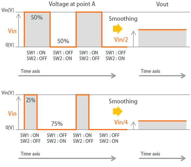
Figure 2-5-3 Voltage control of step-down DC-DC converter
We hope that this helps you understand that switching control can be used to control the output voltage. However, when selecting a power inductor, you must understand how the power inductor specifications affect the efficiency and noise. To explain this, we must also explain the current flowing to the inductor.
Next, we will talk about the inductor current. As described before, the power inductor is used to smooth the pulse voltage, but it actually has another important purpose. This role uses the self-induction characteristic of inductors. As shown in Figure 2-5-2, for the current Iout supplied from the input side when SW1 is turned ON, the input power supply is isolated at the instant that SW1 is turned OFF, and so it appears as if Iout cannot be supplied. A power inductor is used to resolve this problem. Due to its self-induction characteristics, the inductor generates an induced electromotive force in a direction that hinders current changes. As a result, this acts so that current continues to flow even if a voltage is no longer supplied to the inductor.
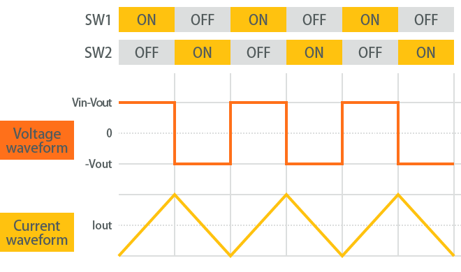
Figure 2-5-4 Voltage and current waveforms of power inductor
Figure 2-5-4 shows the voltage waveform and current waveform applied to the power inductor during DC-DC converter operation. When SW1 is turned ON, a current flows to the inductor from the input power supply. At this state, the current increases proportionally with the time, and the stored energy also increases. When SW1 is turned OFF, the voltage at the input side becomes 0 (V), but due to the characteristics of the inductor, the current does not stop immediately. Instead, it continues to flow and decreases proportionally with the time. You can think of it as the energy that was stored while SW1 was ON is being released when SW1 is turned OFF.
In this way, the power inductor works so that the inductor current flows continuously, and this appears as a triangular waveform. The size of the amplitude of the triangular wave current that flows to the inductor is expressed by the following formula.
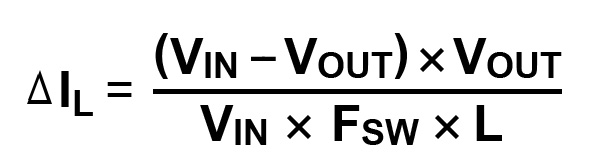
How do the parameters in the above formula affect the operating current waveform?
One of the web tools provided by Murata is the Murata DC-DC Converter Design Support Tool. This tool can be used to select the power inductors and laminated ceramic capacitors suitable for the operating conditions of the DC-DC converter. We can use this tool to see how the parameters affect DC-DC converter operation.

Figure 2-5-5 Example of Murata DC-DC Converter Design Support Tool
Let's simulate how the parameters fluctuate when the standard conditions are set as shown below. (The graph is plotted by exporting the simulation tool calculation results to a CSV file.)
<Standard conditions>
- Vin
- 3.6V
- Vout
- 1.8V
- Frequency
- 2MHz
- Iout
- 1.5A
- L
- 1.0μH
Vin and Vout are parameters that determine the size of the voltage applied to the inductor and the duty ratio. This shows that, when Vout fluctuates, the voltage waveform changes in multiple ways (Figure 2-5-6). This also shows that the frequency changes due to fluctuations in other parameters, but the voltage size and duty ratio do not change. The current waveform also changes due to this voltage fluctuation.
If Vin and Vout become large, the amount of change in the current, which changes over time, also tends to become large, and so the ripple current ⊿I becomes larger.
When the inductance and frequency fluctuate, the voltage size does not change, but this affects the size of the ripple current. When the inductance becomes large, the change in current is reduced, and so the ripple current becomes smaller (Figure 2-5-7). Also, when the frequency becomes large, this shortens the time for one cycle, and so the ripple current becomes smaller (Figure 2-5-8).
When Iout fluctuates, changes are not observed in the waveform of the triangular wave current, but the average value of the current changes based on the size of Iout (Figure 2-5-9).
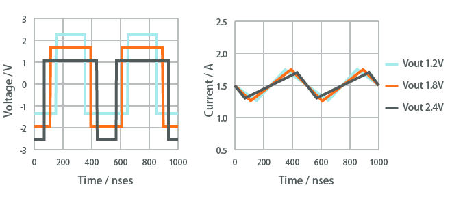
Figure 2-5-6 Voltage and current waveforms when Vout fluctuated
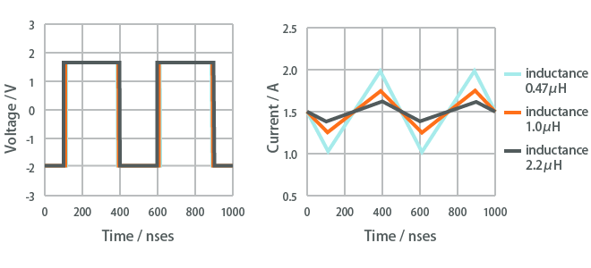
Figure 2-5-7 Voltage and current waveforms when inductance fluctuated
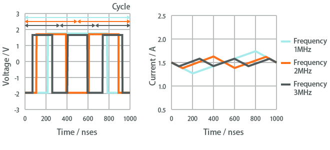
Figure 2-5-8 Voltage and current waveforms when frequency fluctuated
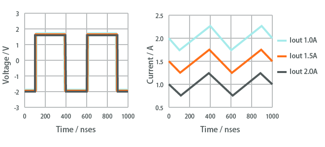
Figure 2-5-9 Voltage and current waveforms when Iout fluctuated
In this way, the waveforms of the voltage and current applied to the power inductor are determined by the conditions of the DC-DC converter and the inductance of the power inductor.
Section 1.2 of the previous chapter describes the inductance and DC superimposition characteristics. If the inductance is too low, the ripple current will become too large, and when the DC superimposition characteristics are poor, the inductance when a large current is applied will drop, and this will ultimately result in a higher ripple current. These inductor specifications have a tremendous impact on operation of the DC-DC converter.
Chapter 2 described the types of DC-DC converters and their operation mechanism.
To find the required characteristics of power inductors, it is extremely important to understand the operation mechanism and inductor current waveform.
Next, in chapter 3, we will examine the relationship of power inductor specifications with DC-DC converter characteristics such as efficiency, ripple current, and load response.