Study of Lead-Free Multilayer Piezoelectric Ceramics with Nickel Inner Electrodes
Shinichiro Kawada, Hiroyuki Hayashi, Hideki Ishii, Tadashi Okuzawa, Masahiko Kimura, Suetake Omiya
Original Paper:
S. Kawada, M. Kimura, Y. Higuchi, and H. Takagi: Appl. Phys. Exp. 2 pp.111401 (2009)
" (K,Na) NbO3-Based Multilayer Piezoelectric Ceramics with Nickel Inner Electrodes".
Piezoelectric actuators and other piezoelectric components feature a compact size and low profile, no electromagnetic noise, and a host of other advantages. For this reason, they are increasingly used for auto-focus actuators in cameras and for other applications. Currently, the only practical piezoelectric materials are lead-based materials, and so lead-based materials are widely used in piezoelectric components.
Although the lead contained in piezoelectric components is not subject to the RoHS directive and other environmental regulations, it is preferable that a lead-free alternative be developed for the future. Also, lead-based piezoelectric materials cannot be co-fired with Ni, and so currently, high-cost Ag/Pd (palladium) is used for the inner electrodes when stacking. Lead-free piezoelectric materials, on the other hand, enable the possibility of use of low-cost Ni. This paper presents our work in successfully fabricating lead-free multilayer piezoelectric ceramics with Ni inner electrodes.
Developing Lead-Free Multilayer Piezoelectric Ceramics
One major issue in piezoelectric components, which are expected to show extensive growth in coming years, is the development of lead-free piezoelectric actuators. Recently, in particular, the demand for low-voltage driving has led to mainstream usage of piezoelectric actuators with multilayer structures, and so the capability for multilayer structures must also be taken into consideration when developing lead-free components. To develop lead-free piezoelectric components that can rival components made from conventional lead-based piezoelectric materials in terms of both performance and cost, we knew that we needed to take advantage of the properties of lead-free piezoelectric materials.
For piezoelectric actuators, it is important to provide large displacement and high reliability at a low cost. Normally, the piezoelectric constant d of the material must be improved to enable large displacement, but lead-free piezoelectric materials generally have a smaller piezoelectric constant d than lead-based piezoelectric materials at approximately the same Curie point TC. However, if a multilayer structure is used, and the number of layers can be increased by making thinner layers, in principle, even if the piezoelectric constant d is low, a displacement amount equal to or larger than conventional materials can be achieved at the same voltage.
Nonetheless, when the same high-cost Ag/Pd inner electrodes as those in conventional lead-based piezoelectric materials are used, the cost of the elements increases substantially as the number of layers increases. One effective way to minimize the increase in cost when adding more layers would be to co-fire with Ni or other base-metal electrodes. High-cost Ag/Pd electrodes are used for conventional lead-based piezoelectric materials because firing in a reducing atmosphere where Ni does not oxidize causes the lead oxide in the ceramic to turn into metal.
Lead-free piezoelectric materials, on the other hand, enable the possibility of co-firing with low-cost Ni. If Ni can be used for the inner electrodes in lead-free piezoelectric materials, this would enable lower costs for the inner electrodes compared to Ag/Pd inner electrodes, and it would enable increasing of the number of layers while still keeping the overall cost of stacked elements to the same level or less of conventional lead-based multilayer piezoelectric ceramics. In addition, in Ag/Pd inner electrodes, Ag migration inside the inner electrodes becomes a problem as the layers become thinner, which can lead to reduced reliability. However, compared to Ag, Ni is less susceptible to migration, and so high reliability can still be attained even if thinner layers than before are used.
For these reasons, if Ni electrodes can be used in the inner electrodes in a lead-free design, combining with thinner layers could enable a large displacement, low cost, and high reliability in lead-free piezoelectric ceramics that are equal to or better than conventional lead-based multilayer piezoelectric ceramics.
Examining the Composition of Lead-Free Piezoelectric Ceramics
Currently, Ni is used in the inner electrodes of monolithic ceramic capacitors. In monolithic ceramic capacitors, the compositional transformation of ceramics having BaTiO3 as the main component allows sintering under a reducing atmosphere for achieving co-firing with Ni inner electrodes. A base composition of BaTiO3 of monolithic ceramic capacitors also has piezoelectric properties, but the Curie temperature is 130°C, which is too low for use in piezoelectric actuators. A Curie temperature of 200°C or higher is preferred for use in piezoelectric actuators. A wide variety of composition types are known for lead-free piezoelectric ceramics having a Curie temperature of 200°C or higher and suitable for piezoelectric actuators, including (K,Na) NbO3-based ferroelectric ceramics, (Bi1/2Na1/2) TiO3-based ferroelectric ceramics, tungsten-bronze structured ferroelectric ceramics, and bismuth layer-structured ferroelectric ceramics. However, in compositions that include Bi as the main component, the Bi2O3 becomes metal Bi when fired in a reducing atmosphere, and so, in principle, co-firing with Ni is difficult to achieve. For this reason, we selected (K0.5Na0.5) NbO3-CaTiO3-based piezoelectric material, which has relatively favorable piezoelectric properties and does not include Bi, as the lead-free piezoelectric material.
To perform co-firing with Ni, at the very least, Ni must be sintered in a reducing atmosphere where Ni does not oxidize for obtaining the piezoelectric properties. This means that, first, firing was performed in a reducing atmosphere in a single-plate shape not including the inner electrodes, and compositions that produced favorable piezoelectric properties were examined. Firing in a reducing atmosphere was performed for the three compositions below with 5mol% of MnCO3 added as a sintering aid.
- 0.96 (K0.5Na0.5) NbO3-0.04CaTiO3+0.05mol MnCO3 (KNN-CT)
- 0.96 (K0.5Na0.5) NbO3-0.04CaZrO3+0.05mol MnCO3 (KNN-CZ-1)
- 0.96 (K0.5Na0.5) NbO3-0.04CaZrO3+0.03molZrO2+0.05mol MnCO3 (KNN-CZ-2)
The density and insulation resistivity that were obtained in the sintered body are shown in Table 1.
|
Sintered body density
kg/m3 |
Insulation resistivity
Ω・m |
| KNN-CT |
4.5×10³ (98%) |
7.7×10⁴ |
| KNN-CZ-1 |
4.0×10³ (87%) |
1.6×10⁶ |
| KNN-CZ-2 |
4.5×10³ (98%) |
6.3×10⁸ |
*The relative density is indicated in parentheses ( ) .
Table 1 Sintered Body Density and Insulation Resistivity of Single Plate Fired in Reducing Atmosphere
After KNN-CT was fired in a reducing atmosphere, a high-density sintered body with a relative density of 98% was obtained, but the insulation resistivity was a low value of 7.7 x 10⁴Ω・m so that polarization could not be performed. Even though the sintered body density was sufficiently high, due to the low insulation resistivity, the Ti valence may have changed when fired in a reducing atmosphere, resulting in disruption of the charge balance.
For this reason, KNN-CZ-1 was fired in a reducing atmosphere where Ti having a fluctuating valence number was replaced by Zr, whose valence number does not fluctuate. This resulted in an insulation resistivity of 1.6 x 10⁶Ω・m, which was higher than KNN-CT, but still was not a level high enough to enable polarization. This was because the KNN-CZ-1 had a sintered body relative density of only 87%, and the low insulation resistivity is thought to be due to incomplete sintering. Various additives were examined for improving the sintering density of KNN-CZ-1, and as a result, a KNN-CZ-2 composition where 0.03mol of ZrO2 was added to 1mol of KNN-CZ-1 showed an improvement of the sintered body relative density to 98% and the insulation resistivity to 6.3 x 10⁸Ω・m, and this improvement was enough so that polarization was possible. The piezoelectric properties of KNN-CZ-2 are shown in Table 2.
|
Dielectric constant
ε33T/ε0 |
Electromechanical-coupling factor
kp/% |
Piezoelectric constant
d33/pC/N |
Curie temperature
TC/°C |
| KNN-CZ-2 |
1180 |
31.8 |
160 |
260 |
Table 2 Piezoelectric Properties of Single Plate KNN-CZ-2 (Fired in Reducing Atmosphere)
As described above, for the KNN-CZ-2 composition, sintering was possible even in a reducing atmosphere, and a piezoelectric ceramic was obtained that showed favorable piezoelectric properties. This led us to actually use KNN-CZ-2 to trial-manufacture multilayer piezoelectric ceramics with Ni inner electrodes by firing in a reducing atmosphere for evaluating the piezoelectric properties of the multilayer body.
Trial Manufacturing and Evaluation of Ni Electrode Multilayer (K,Na) NbO3-Based Ceramics
KNN-CZ-2, which can be sintered in a reducing atmosphere, was used to trial-manufacture multilayer KNN-CZ-2 ceramics with Ni inner electrodes. An SEM (scanning electron microscope) image of the sintered body surface of the obtained multilayer KNN-CZ-2 ceramics with Ni inner electrodes is shown in Fig. 1, and an SEM cross-sectional image is shown in Fig. 2. Figure 1 shows that a ceramic having microscopic grains with an average particle diameter of 0.7µm and without any abnormal grain growth was obtained. Furthermore, Fig. 2 shows that fine-grain ceramics without any pores were obtained.
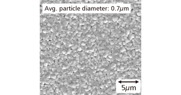
Fig. 1 SEM Image of Sintered Body Surface of Multilayer KNN-CZ-2 Ceramics with Ni Inner Electrodes
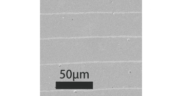
Fig. 2 SEM Image of Sintered Body Cross-Section of Multilayer KNN-CZ-2 Ceramics with Ni Inner Electrodes
Next, the ceramics were polarized by applying an electric field of 3.0kV/mm in oil at 80°C for 0.5 h. An electric field was applied to the multilayer KNN-CZ-2 ceramics with Ni inner electrodes that was polarized, and the displacement in the thickness direction when applying the electric field was measured using a displacement meter (Mahr Millitron 1202D) . The maximum strain Smax that was obtained was divided by the maximum electric field Emax that was applied to find the strain characteristic Smax/Emax. The electric field-strain curve of the multilayer KNN-CZ-2 ceramics with Ni inner electrode is shown in Fig. 3, and the electric-field dependence of the strain characteristic Smax/Emax is shown in Fig. 4. The strain characteristic Smax/Emax showed a maximum value of 360pm/V when an electric field of 2kV/mm was applied, and in the range from 1 to 3 kV/mm, the characteristic was nearly constant. The strain when applying a large electric field was about 1/3 of that for the current lead-based multilayer ceramics with Ag/Pd inner electrodes.
Next, the ceramics were polarized by applying an electric field of 3.0kV/mm in oil at 80°C for 0.5 h. An electric field was applied to the multilayer KNN-CZ-2 ceramics with Ni inner electrodes that was polarized, and the displacement in the thickness direction when applying the electric field was measured using a displacement meter (Mahr Millitron 1202D) . The maximum strain Smax that was obtained was divided by the maximum electric field Emax that was applied to find the strain characteristic Smax/Emax. The electric field-strain curve of the multilayer KNN-CZ-2 ceramics with Ni inner electrode is shown in Fig. 3, and the electric-field dependence of the strain characteristic Smax/Emax is shown in Fig. 4. The strain characteristic Smax/Emax showed a maximum value of 360pm/V when an electric field of 2kV/mm was applied, and in the range from 1 to 3 kV/mm, the characteristic was nearly constant. The strain when applying a large electric field was about 1/3 of that for the current lead-based multilayer ceramics with Ag/Pd inner electrodes.
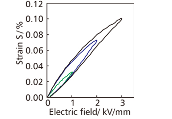
Fig. 3 Electric Field-Strain Curve of Multilayer KNN-CZ-2 Ceramics with Ni Inner Electrodes
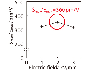
Fig. 4 Electric-Field Dependence of Strain Characteristic of Multilayer KNN-CZ-2 Ceramics with Ni Inner Electrodes
Conclusion and Future Issues
We found that we were able to obtain favorable piezoelectric properties even after firing in a reducing atmosphere by adding 0.05mol of MnCO3 and 0.03mol of ZrO2 to 0.96 (K0.5Na0.5) NbO3-0.04CaZrO3. Using the same composition, we performed co-firing with Ni inner electrodes to trial-manufacture lead-free multilayer piezoelectric ceramics with Ni inner electrodes. The strain characteristic Smax/Emax of the obtained lead-free multilayer piezoelectric ceramics with Ni inner electrodes was 360pm/V when applying an electric field of 2kV/mm, and this was about 1/3 of the value for current lead-based multilayer ceramics with Ag/Pd inner electrodes. Therefore, if the thickness of a single layer can be made to 1/3 of current lead-based multilayer ceramics with Ag/Pd inner electrodes, a displacement amount equivalent to lead-based ceramics can be attained by using lead-free multilayer piezoelectric ceramics with Ni inner electrodes.
Although it is possible to attain an equivalent displacement amount by using thinner layers in lead-free multilayer piezoelectric ceramics with Ni inner electrodes, a large number of unexamined issues still remain. First, when thinner layers are used to satisfy the displacement characteristics, the increased capacity due to the thinner and higher quantity of layers can cause issues where the current increases when elements are driven. For this point, design and driving methods need to be examined so that both the displacement characteristics and driving current satisfy the required characteristics. Furthermore, the reliability and mechanical strength have yet to be fully examined, and so these issues need to be investigated concurrently with the development of thinner layers.