Next Generation Multilayer Ceramic Capacitors – Understanding the Challenges Faced when Developing Capacitors and How they Affect Your Next Design
Capacitors are one of the fundamental passive electronic components and on the surface seem incredibly simple. However, the challenges of capacitor design and their implementation could not be more complex. Advanced electronic systems such as computer processors and system-on-chips (SOC) all involve incredibly intricate applications of capacitors, each design with unique electronic specifications and packaging constraints.

A common theme shared across most modern electronics is the continual demand for increasing capacitor charge storage density. With this focus on smaller physical size, for a given capacitance, comes the increasing challenge of ensuring reliability. This is especially true for systems with a challenging thermal environment, where repeated heat cycles can drastically shorten the component’s life. As is often the case in engineering, the challenge manufacturers face when developing capacitors is balancing these counteracting considerations.
Understanding Capacitors
So how do we achieve greater capacity and ensure that reliability is not compromised? First, you must understand how the core physical elements of a capacitor contribute to its capacitance and the possible areas for improvement. This requires detailed knowledge of both a capacitor as a component and its associated manufacturing processes. Murata has been working with passive components since the company’s inception over 70 years ago and one area where they have seen continued improvement is in multilayer ceramic capacitors (MLCCs). Since 1995, they have reduced the thickness of its dielectrics from around 3µm in 1995 to less than 0.5µm now. This has progressively improved the volumetric efficiency of its MLCCs, which directly increases the overall capacitance. Consequently, the thinner dielectrics amplify the strength of the electric field between the capacitors’ plates, as well as the voltage stress on the dielectric material. Realizing a gain in charge density hence needs new dielectric materials that can withstand the increased voltage stresses while also maintaining long-term reliability.
Conventional techniques to thin dielectric and inner electrode layers can lead to capacitors with reduced withstanding voltages and reliability, as well as increasingly voltage-dependent performance characteristics. Murata’s technique allows for thinner ceramic dielectrics with a more homogeneous and compact dielectric layer, while atomizing the nickel powder electrodes allows for more consistent electrode layers with increased packing factors.
Material Selection and Processing
For manufacturers, the way a material is processed is as important as the choice of the material. Changing the size of the grains of a BaTiO3 dielectric, and hence the number of grain boundaries in each dielectric layer, can alter the reliability of a capacitor.

As you can see in Figure 1, using the X7R dielectric material as a baseline, by halving the thickness of the dielectric layer, it also halves the number of grain boundaries per unit area, undermining the reliability. Alternatively shrinking the grain size from 200nm to 100nm, while maintaining the reduced thickness, creates an equivalent number of grain boundaries per unit area as the baseline example and maintains reliability. Shrinking the grain size creates another interesting design consideration – as the grain size reduces, so does the components ‘core’ volume, altering its capacitance characteristics at high temperatures. A capacitor’s reliability is inversely proportional to the capacitance change at high temperatures. This is because, although using smaller grains in the dielectric decreases the core size, the smaller grains also allow for better insulation characteristics, increasing reliability at the cost of peak thermal drop-off performance.
Exploring Capacitor Characteristics
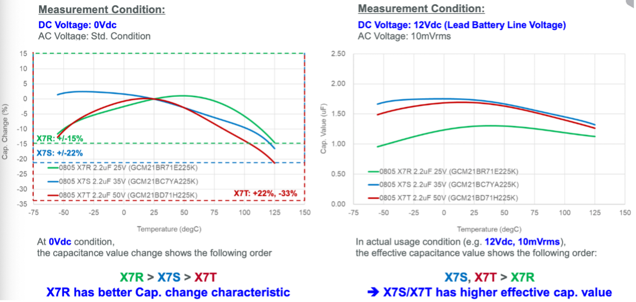
When selecting a component, it is important to understand the real-world performance. In the left-hand example, at 0Vdc the larger grain X7R has a better capacitance change characteristic. But if we look at the right-hand graph, under real-world representative 12V DC, 10mVrms AC conditions, both the X7S and X7T have a higher effective capacitance performance at any given temperature. Showing that thanks to their higher charge density, the small grain capacitors have an increased performance in most conditions, as well as improved reliability brought about by their construction.
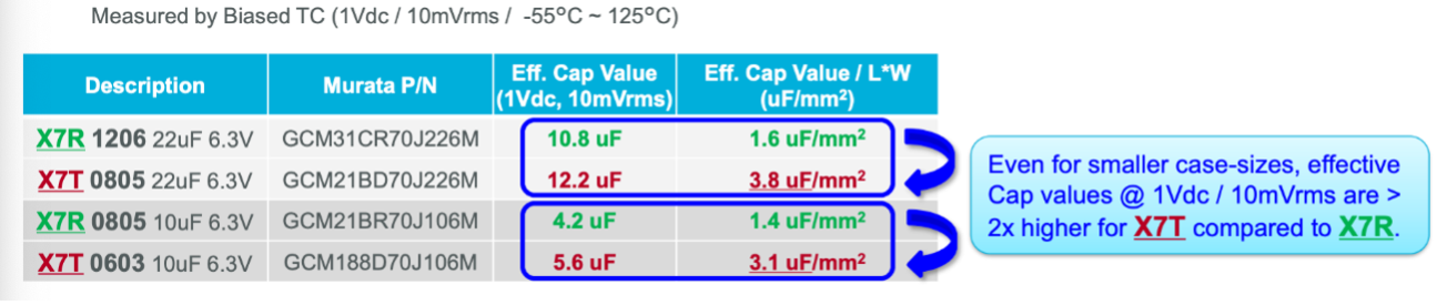
In Figure 3, we can clearly see the improvement achieved by moving to a smaller grain, with an effective capacitance value per area gain of over 2x higher for the X7T model.
Implementing High Performance MLCCs
Despite their simple appearance, the factors under consideration when developing capacitors are incredibly complicated. Equally, implementing high-performance capacitors, particularly MLCCs, also needs careful examination. You must deliberate complex trade-offs in their performance to specify them effectively. To help designers, Murata has created an online tool called SimSurfing. Here, you can use the platform to explore the effect of these trade-offs within your real-world designs.
In terms of applications, the demands of high-performance applications are pushing manufacturers to increase the volumetric efficiency of the devices they offer, while testing reliability limits. Through Murata’s production methods, it is possible to maintain reliability while increasing volumetric efficiency. These smaller components, while an equivalent capacity to previous generations, can under certain conditions have a greater derating of capacitance at high operating temperatures. In most cases, the extensively engineered Murata’s X7S/X7T MLCCs will provide higher effective capacitance values per unit volume than previous generations in real-world conditions, while offering the same or higher reliability. But it is always key for designers to understand what the device’s effective capacitance will be under their application’s actual usage voltage and operating temperature, as to make the best component selection.