4-4. Noise shield
Section 4-2-1 described that a shield is used to block out the spatial noise
conduction. In many cases, this shield works as an electromagnetic shield. This
section describes general characteristics of electromagnetic shield and explains
several points to be kept in mind for effective use.
4-4-1. Shield configuration
(1) Shield of electronic devices
Shields used for electronic devices are implemented in a way to cover up the
body, circuit board or cable as shown in the figure below. This section will
focus on the sections where noise penetrates those shields as shown in the
figure and describe the effects of the electromagnetic shields to block out
radio waves based primarily on the material characteristics.
Shields are not only used for noise emitting to the outside but also used for
external noise entering into the circuit. Just like the case of antenna, since
these two effects are the same, the section will only focus on the noise
emission.
Fig. 4-4-1 Example of shield configuration for electronic devices
(2) Breakdown of shielding effect
As shown in Fig. 4-4-1, the effect from confining noise with a shield can be
generally explained by using the Schelkunoff's formula.
As shown in 4-2-2, the shielding effect for radio waves hitting the shield from
the left side and leaking out to the right side is considered. Here, we assume
that the radio waves leaking out to the right side are weaker than the radio
waves hitting from the left side by SE (dB). The Schelkunoff's formula expresses
the shielding effect SE by summing three terms as below.
(Formula 4-4-1)
-
R
Loss of radio waves by reflection at the surface (reflection loss)
-
A
Loss of radio waves by attenuation inside the shield (attenuation loss)
-
B
Effect of multiple reflection between the front side and back side (multiple
reflection effect)
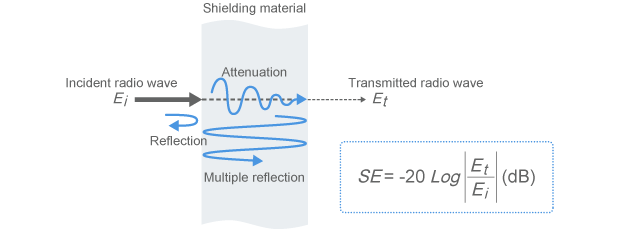
Fig. 4-4-2 Shielding effect
Of these, the multiple reflection effect B is ignored here, since it has only
small influence except under a special condition of very small absorption loss
of A.
Although the Schelkunoff's formula is an approximation formula, it has
practically sufficient accuracy and is widely used because it is useful for
understanding the shielding effect. Please refer to technical books
[Reference 3]
for details. This section will further describe the general shield properties
based on this formula.
4-4-2. Shield properties
(1) Shielding effect of about 100dB with a very thin plate as long as it is made
of metal
Fig. 4-4-3 shows a case of copper plate as an example of calculation results
that use the Schelkunoff's formula.
Fig. 4-4-3 Shielding effect of copper plate
Fig. 4-4-3(a) represents the frequency characteristics with a thickness of
0.1mm. The shielding effect SE indicated by a red line reaches 100dB or more in
the entire range from 0.1 to 1000MHz. In case of noise suppression for general
electronic devices, 100dB is considered to have a sufficiently large effect.
Fig. 4-4-3(b) shows calculation results by changing the thickness with a fixed
frequency of 10MHz. Even a very thin copper plate of 10
µ
m thickness can have a substantial shielding effect. The breakdown of the effect
is explained below.
(2) Reflection loss
The blue line in Fig. 4-4-3 represents the reflection loss R. It is understood
from the figure that copper has an effect of nearly 100dB solely from the
reflection loss.
The reflection loss occurs due to very bad impedance matching between the
intrinsic impedance of space and the intrinsic impedance of shielding material
when radio waves are transmitted from the left to the right as shown in Fig.
4-4-4. The intrinsic impedance of space is 377 ohms, while the intrinsic
impedance of copper plate is only 1.17 milliohms at 10MHz. The difference is
indeed 320,000 times. Therefore, the energy of the radio waves can hardly enter
into the copper plate.
The intrinsic impedance here represents the property of radio waves transmitting
as plane waves inside a specific material and indicates the amount equivalent to
the characteristic impedance of the transmission line. It represents the ratio
of the electric field to the magnetic field and is a value determent by the
dielectric constant
ε
, magnetic permeability
µ
, conductivity
σ
and frequency
ƒ
, etc.
Generally, since metals have an extremely high conductivity, the intrinsic
impedance becomes very small.
Although Fig. 4-4-3 shows the case of copper, iron has a conductivity one order
smaller and a magnetic permeability 1000 times higher. So the reflection loss is
more or less smaller. However, it still has a reflection loss of nearly 60dB at
10MHz. Therefore, most metal materials are considered to be able to achieve a
reflection loss that causes no practical problems. This reflection loss can be
achieved regardless of the thickness. (If the thickness is extremely thin, a
correction for the multiple reflection effect is required)
Since the reflection is caused by the conductivity, it also means that the
shielding effect can be reduced at a section where the resistance is high (if
any). For example, in case that there is a joint in the shielding plate, any
resistance at the connected section can significantly reduce the shielding
effect. In order to ensure the conduction of connected section, a conductive
gasket etc. may be used.
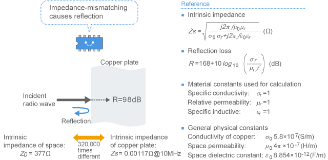
Fig. 4-4-4 Reflection of radio wave at the surface of shielding plate
(3) Attenuation loss
The green line in Fig. 4-4-3 represents the attenuation loss. This loss tends to
sharply increase as the frequency and/or material thickness increase(s).
Therefore, in case of Fig. 4-4-3(a) for example, the attenuation loss exceeds
the reflection loss in the frequency range of 100MHz or more, achieving an
extremely large shielding effect of 200dB or more in total.
Fig. 4-4-5 Attenuation of radio wave inside the shielding plate
The attenuation loss is an attenuation of radio waves due to a property
generally known as the skin effect. When radio waves enter into a metal, the
radio waves are characteristically attenuated by a factor of 0.37 at the skin
depth of
δ
from the surface. Therefore, if the shielding plate is thicker than the skin
depth, a significant effect can be expected.
When using shielding materials with the same thickness, the material with a
thinner skin depth is considered to have a better attenuation loss. Fig. 4-4-6
shows calculation results of skin depths for general shielding materials
(copper, aluminum and iron). The higher the frequency, the thinner the skin
depth becomes, and thus the attenuation loss can be expected. At 10MHz, the
attenuation loss can be expected from copper with a thickness of 20
µ
m or more and from iron with a thickness of 2
µ
m or more.
The skin depth also varies depending on the magnetic permeability
µ
and conductivity
σ
of the material. The higher the conductivity or magnetic permeability, the
thinner the skin depth becomes. Although Fig. 4-4-6 indicates that iron has a
lower conductivity than copper, iron has a skin depth one order thinner than
copper due to its overwhelmingly large magnetic permeability. Therefore, it is
understood that iron is a material with a large attenuation loss even though its
reflection loss is smaller than copper. (Since Fig. 4-4-6 assumes that the
relative permeability of iron is 1000, it is not quite accurate)
Fig. 4-4-6 Skin depth of metal plate
(4) Material parameters that affect the shielding effect
When a metal plate is used as above, a larger effect can be gained by:
-
(i)
using a thicker shielding material (the attenuation loss increases)
-
(ii)
increasing the conductivity (both attenuation loss and reflection loss
increase)
-
(iii)
increasing the magnetic permeability (the attenuation loss increases)
Usually, as long as it is a metal plate, any materials or thickness can exert
practically sufficient shielding effect. However, if you are dealing with a
frequency range of 100kHz or lower in the vicinity of a loop antenna as
described below, the material and thickness may be important.
4-4-3. Shield of low frequency magnetic field
As shown in the calculation results of Fig. 4-4-6, the skin depth increases as
the frequency decreases. Therefore, when using a thin metal plate of about 0.1mm
thickness, a large attenuation loss cannot be expected from copper or aluminum
in the range of 1MHz or lower and from iron in the range of 10kHz or lower.
Shielding such low frequency noise with the attenuation loss requires a
substantially thick material.
As mentioned in the previous section, we are supposed to be able to expect
sufficiently large shielding effect from the reflection loss in normal cases
even without the attenuation loss. However, this is on the premise that the
intrinsic impedance of material is extremely smaller than the intrinsic
impedance of space.
In fact, when the shielding material is placed in the vicinity of a noise
antenna, the wave impedance (ratio of the electric field to the magnetic field)
is different from the intrinsic impedance of space (377 ohms). Please refer to
Section 4-4-2 for the wave impedance in the vicinity of an antenna. The
reflection loss of the shielding material placed in the vicinity of an antenna
varies depending on this wave impedance.
Particularly in the case of Fig. 4-4-7, the magnetic field is strong in the
vicinity of loop antenna, making the wave impedance way less than 377 ohms.
Therefore, the impedance-mismatching with the intrinsic impedance of the
shielding material is reduced, and thus reducing the reflection loss. Therefore,
the attenuation loss needs to be increased for compensating the reduction.
However, since the skin depth increases in the low frequency range, a fairly
thick material needs to be used.
For the above reason, it is hard to shield low frequency noise in the vicinity
of loop antenna by using a good conductor such as copper. In such a case, an
iron plate (thinner skin depth) is more suitable than a copper plate. In
addition, a magnetic shielding technique may be required apart from the
electromagnetic shield.
Fig. 4-4-7 Difficult to shield low frequency
magnetic field
4-4-4. Connection of shielding case
As explained above, the shielding effect of a material can be estimated by the
Schelkunoff's formula. However, when it is applied to actual electronic devices,
you are usually not able to gain the effect as described here. The primary
reason is that any connected section or opening may become a bottleneck and
somehow interfere with getting sufficient material performance. This section
explains several points to be kept in mind for connecting a shielding case.
(1) When assembling a shielding case
As described above, the shielding effect of a metal plate is primarily generated
by the conductivity. That is to say, it is important that the current can easily
flow through the shield surface. If there is an opening or gap in the shield
surface, it is hard for the current to flow through, and thus impairing the
shielding effect.
As shown in Fig. 4-4-8, the connected section of a shielding case should be
firmly attached. A good shielding can be maintained by seamlessly connecting the
shield surfaces with use of conductive gaskets etc. If you are only using screws
or contact points for making connections, the interval between screws or contact
points should be reduced (to about 1/20 of wavelength).
If there is still a gap in the shielding case as shown in Fig. 4-4-9, you need
to be aware that radio waves are likely to be emitted particularly at the
frequency that makes the gap length form 1/2 wavelength. (For example, in the
case of 12cm CD slot, it will be approx. 1.2GHz.)
Fig. 4-4-8 Connection of shielding case
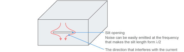
Fig 4-4-9 Effect of a slit opening
(2) Factors other than radio wave shield
If the shield is broken due to an opening in the shield, incomplete enclosure of
the entire object, or a wire protruding from the shield, the shielding case
itself becomes an antenna and emits radio waves. In this situation, you may say
that the common mode noise has been induced to the shield.
This phenomenon is different from the problem where the opening shown in Fig.
4-4-9 works as an antenna. The entire shielding case or the entire system works
as an antenna as shown in Fig. 4-4-10(a). Since the antenna becomes a large
size, the frequency of the nose emitted will be lower that the frequency
estimated from the size of the opening.
The energy is not so high, since it is driven by floating electrostatic
capacitance etc as described in Fig. 4-4-10(a). However, you need to be aware of
this possibility if a complete shielding is required.
As described in Fig. 4-4-10(b), in order to prevent this from happening, you
need to:
-
(i)
insert a filter if a wire is protruding
-
(ii)
reduce the size of opening if the opening is the cause of problem, or keep
the internal noise source away from the opening
-
(iii)
increase the enclosure if the entire object has not been enclosed.
These methods are also effective for ground enforcement
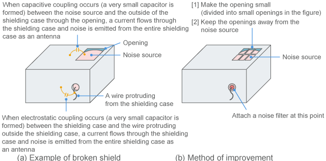
Fig 4-4-10 Improvement for sections with
broken shield
4-4-5. Connection of shielded cable
(1) Ground of shielded cable
Although you may say that the primary function of shielding case is "confining
the noise inside", the shielding part of a shielded cable may also work as a
path for current. Therefore, extra care needs to be taken for the section where
the shield is connected to the ground.
An example of the shielding part that works as a path for current is a coaxial
cable shown in Fig. 4-4-11. As you know, a coaxial cable can be used as a
shielded cable. It is also an ideal transmission line. The outer conductor
(outer sheath) is a return circuit of signal current.
In terms of shield connection to the ground, the same concept is applicable to
general shielded cables other than coaxial cables. Although the return circuit
of current and the shield may be clearly separated in some cases, the common
concept can be applied to the noise suppression for general electronic devices.
Therefore, this section explains the shield connection with reference to coaxial
cable as an example.
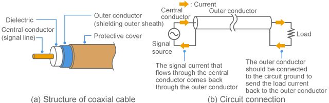
Fig. 4-4-11 Coaxial cable
To transmit a signal through a coaxial cable, the outer sheath should be
connected to the circuit ground as shown in Fig. 4-4-11(b). This allows
cancelling out the electromagnetic field caused by the current flowing through
the inner conductor with the current flowing through the outer conductor,
eliminating the noise emission from the cable.
For a general shielded cable, the shielded cable should be connected to the
ground at both ends. However, for an electrostatic shield, only one end may be
connected in some cases.
(2) Connection to shielding case
How should we connect the shield of this cable to the shielding case? Fig.
4-4-12 shows a schematic diagram that connects two shielding cases with each
other.
As shown in Fig. 4-4-12, in order to achieve the complete shield connection, the
entire circumference of the outer sheath of the shielded cable needs to be
connected to the shielding case. For this purpose, shielded connectors are
usually used.
If both shielding cases have been connected to the earth ground separately, it
might cause a ground loop or it might not be able to comply with the principle
of single point ground as shown in Fig. 4-4-12. These facts go against the
general design policies for eliminating noise interferences in a relatively low
frequency range. That is to say, pursuing the shield for eliminating noise
emission could actually lead to increase low frequency noise.
As described above, noise suppression may have a trade-off relationship
depending on the status of ground connection, and there is still a possibility
of not being able to avoid handling noise case by case. (For example, if the
earth ground is disconnected on one side in Fig. 4-4-12, the above problem is
resolved, while it could increase the risk of electrification or could
compromise the susceptibility to static electricity)
Fig. 4-4-12 Connection to shielding case
(3) Connection to circuit board
Although there are problems as explained above, the ground of a shielded cable
is in general firmly connected to the shielding cases on both ends as shown in
Fig. 4-4-12 and is then connected to the circuit ground. This allows:
-
(i)
providing a shield structure integrated with the shielding cases against
noise, and
-
(ii)
providing a correct current feedback circuit for the signal.
Fig. 4-4-13 shows the connection to a circuit board with reference to coaxial
cable as an example.
Fig. 4-4-13(a) shows a case of connecting a wire to a circuit board. The
shielding outer sheath of the cable is connected to the shielding case by a
coaxial connector. This allows making a correct shield structure.
Fig. 4-4-13(b) shows that a gap between the coaxial connector and circuit board
is also connected by a short coaxial cable. In this case, you can create an even
better circuit for the signal transmission. Please note that the ground of the
coaxial cable should also be connected on the circuit board side.
Fig. 4-4-13 Ground of shielded cable
4-4-6. Example of inappropriate shield
(1) Pigtail
As an example of incorrect ground connection for shielded cable, there is a
structure called "pigtail". This is a method of connecting the shielding outer
sheath to the ground by bundling it like a wire as shown in Fig. 4-4-14(a). It
is easy to make connection. But the bundled part generates impedance and impairs
the shielding effect.
Fig. 4-4-14(b) shows an example of pigtail connected to the shielding case. In
this case, the connection destination is appropriate for shielding noise.
However, the shielding effect has been impaired by the pigtail. In addition,
there is no return path for the signal current (the figure shows that the
current returns through the ground of shielding case that is relatively far
away). In such a case, noise may be induced to the ground by the signal current,
and thus the shielded cable can work as an antenna for this noise.
Fig. 4-4-14(c) shows an example of pigtail connected to the circuit ground side.
In this case, the return path of the signal current is appropriate. However, the
the shielding case and the ground of the shielded cable have been separated from
each other. Therefore, the shielding effect is significantly impaired.
Fig. 4-4-14 Example of inappropriate ground
(2) How to improve pigtail
Actually, the connection shown in Fig. 4-4-14(c) is inevitably performed as a
general method when there is no shielding case or when it cannot be connected to
the shielding case due to the principle of single point ground. Although it is
not recommended in case you need to substantially eliminate noise, Fig. 4-4-15
shows a method to improve this situation.
Fig. 4-4-15(a) is a case that the signal is substantially shielded. A dedicated
connector is used for the connection between the circuit board and coaxial
cable. If the ground of this circuit board is stable, the function of the cable
shield will be relatively efficient.
In order to stabilize the ground of the circuit board, the circuit ground should
be connected to the shielding case (if any) at the base of the cable (nearest
possible) as shown in the figure. If you cannot make connection due to the
design policy of single point ground, it should be connected via a capacitor as
shown in the figure.
Fig. 4-4-15(b) is an example of noise suppression with an EMI suppression
filter. Since the shield has been broken at the part exposed from the shielded
cable, a filter is attached at this point to block out noise going in and out.
Although the figure shows a coaxial cable, a common mode choke coil is used for
this part in case of differential signal.
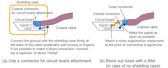
Fig. 4-4-15 Example of improving the ground
(3) Broken shield
If the shielding outer sheath of a shielded cable is broken, what effects may be
caused? For example, if there is a fissure in the circumferential direction as
shown in Fig. 4-4-16(a), it would cause a serious impact if it goes through the
entire circumference even if it is a very small gap. This is because the shield
current that is flowing in the length direction is interfered. Even if it is
just a single fissure, the effect of the entire cable is impaired.
If there is a fissure in the longitudinal direction as shown in Fig. 4-4-16(b),
it would not interfere with the shield current, causing a relatively less
impact.
Fig. 4-4-16 Example of fissure in shielded
cable
“4-4. Noise shield” - Key points
-
Shielding effect is formed by the reflection loss and attenuation loss
-
In most cases, it has a sufficient effect with a thin metal plate
-
The shield of shielded cable should be connected to the shielding case
all along the circumference